- 4 -
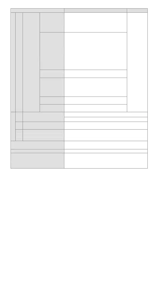
Item Specification Note
ELC external
interrupt
I000/I001 (X0), I100/I101(X1), I200/I201
(X2), I300/I301 (X3), I400/I401 (X4),
I500/I501 (X5),
6 points (01: rising-edge trigger; 00:
falling-edge trigger)
ELC2 external
interrupt
I000/I001 (X0), I100/I101 (X1), I200/I201
(X2), I300/I301 (X3), I400/I401 (X4),
I500/I501 (X5),
I600/I601 (X6), I700/I701 (X7)
I910/I911 (X10), I920/I921 (X11)
I930/I931 (X12), I940/I941 (X13)
I950/I951 (X14), I960/I961 (X15)
I970/I971 (X16), I980/I981 (X17)
16 points (01: rising-edge trigger; 00:
falling-edge trigger)
Time interrupt
I601~I699 (1ms), I701~I799 (1ms),
I801~I899 (0.1ms)
Interrupt when
high-speed
counting
reaches its
target
I010, I020, I030, I040, I050, I060, 6 points
Interrupt during
pulse output
I110, I120, I130, I140, 4 points
Index
I
Interrupt
subroutine
Interrupt during
communication
I150, I160, I170, 3 points
Position
index for
interrupt
subroutine
K-32,768 ~ K32,767 (16-bit operation)
K Decimal
K-2,147,483,648 ~ K2,147,483,647(32-bit operation)
H Hex
H0000 ~ HFFFF (16-bit operation), H00000000 ~
HFFFFFFFF (32-bit operation)
Constant
F Floating point
Displaying floating points by the length of 32 bits with
IEEE754 standard
±1.1755 × 10-38 ~ ±3.4028 × 10+38
Serial communication ports
(program write in/read out)
COM1: RS-232; COM2: RS-485 (Client/Server)
COM1 and COM2 can be used at the same time
Potentiometer / RTC Built-in 2 points VR / Built-in RTC
Special extension module
Right-side extension module and PB series share all
modules (max. 8 modules extendable)
Left-side can be connected with new high-speed
extension modules (max. 8 module extendable)
*1: Non-latched area cannot be modified.
*2: The preset non-latched area can be modified into latched area by setting up
parameters.
*3: The preset latched area can be modified into non-latched area by setting up
parameters.
*4: The fixed latched area cannot be modified.
After the 24V DC power is switched off, the data in the latched area is stored in SRAM
memory which is powered by the rechargeable battery. When the battery is damaged or
cannot be changed, the data in the program and latched area will be lost. If the user
needs to permanently save the data in the latched area in the program and device D,
please refer to “Flash ROM permanently saved and recover mechanism” as stated
below.
Permanently saved mechanism:
The user can use ELCSoft (Options -> ELC<=>Flash) to indicate whether to
permanently store the data in the latched area in the program (including password) and
device D in Flash ROM memory (new indicated data will replace all data previously
saved in the memory).
Recover mechanism:
If the rechargeable battery is in low voltage, resulting in the loss of data in the program,
ELC will automatically restore the data in the latched area in the program and device D
of Flash ROM into SRAM memory (M1176 = On) next time when 24V DC is re-powered.
The ERROR LED flashing will remind the user that if the recorded program is able to
resume its execution, the user only needs to shut down and re-power the ELC once to
 Loading...


