IF 1767 • 09/15 Copyright
©
2015, Eaton’s Crouse-Hinds Division Page 10
6.2 POWER LOSS (HEAT DISSIPATION)
When the ACE Series enclosure is not installed in a well ventilated area,
provisions must be made to account for heat generation and ensure
proper operation of the device.
6.3 DE-RATING FACTORS
The final drive output rating is a multiplication of all applicable de-rating
factors.
Factors are given as a percentage of rated output current.
6.3.1 AMBIENT TEMPERATURE DE-RATING
As standard, each drive is rated for its full output current in
CT/IH (Constant Torque with High Overload) at 50°C ambient
temperature*.
For ambient temperatures above 50°C and not exceeding 60°C, the
de-rating is 5% per °C. *100HP is rated for full output current at 40°C.
6.3.2 ALTITUDE DE-RATING
At altitudes from 1,000m to 3,000m (3280ft to 9840ft) above sea level,
the de-rating is 1% per 100m (328ft).
NOTE: If the installation site is higher than 2,000m (6,560ft) above sea
level, connection of the drive to an ungrounded (IT) or corner-grounded
delta network is not allowed.
6.3.2 SWITCHING FREQUENCY DE-RATING
To reduce motor noise, a higher switching frequency may be desired.
Note that this will increase heat output from the drive.
For switching frequencies above the factory default, the de-rating is 6%
per 1kHz.
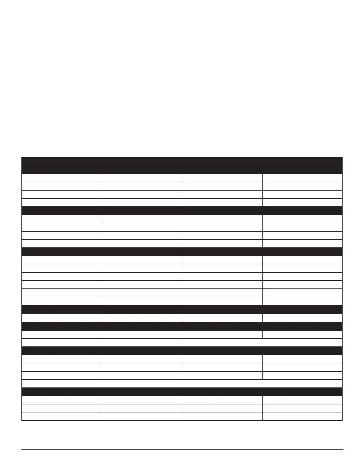
PARAMETER NUMBER PARAMETER DESCRIPTION VALUE VALUE DESCRIPTION
BASIC PARAMETERS – P1
P1.10 LOCAL/REMOTE SELECT 1 LOCAL CONTROL
P1.11 REMOTE 1 CONTROL PLACE 0 I/O TERMINAL
P1.12 LOCAL CONTROL PLACE 1 I/O TERMINAL
P1.13 LOCAL REFERENCE 6 KEYPAD
DIGITAL INPUT – P3
P3.1 START/STOP LOGIC 3 START PULSE-STOP PULSE
P3.2 START SIGNAL 1 2 DigIN:1
P3.3 START SIGNAL 2 3 DigIN:2
P3.8 FAULT RESET 5 DigIN:4
DIGITAL OUTPUT – P5
P5.2 RO1 FUNCTION 2 RUN
P5.3 RO2 FUNCTION 3 FAULT
P5.4 RO3 FUNCTION 41 TEMP LIMIT SUPERV
P5.15 TEMP LIMIT SUPV 2 HIGH LIMIT
P5.16 TEMP LIMIT SUPV VAL 40.0 DEG C
P5.35 RO3 OFF DELAY 30 SEC
MOTOR CONTROL – P8
P8.10 SWITCHING FREQUENCY 4.0 (3.6 on 100HP model) kHz
PROTECTIONS – P9
P9.39 COLD WEATHER MODE 1 YES
POTENTIOMETER OPTION (SUFFIX PT) ONLY
P1.13 LOCAL REFERENCE 0 AI1
P2.1 AI1 MODE 1 0-10V
P2.2 AI1 SIGNAL RANGE 0 0-100%
LOCAL/REMOTE SWITCH OPTION (SUFFIX LR) ONLY
P3.21 REMOTE CONTROL 9 DigIN:8
P3.22 LOCAL CONTROL 8 DigIN:7
P3.42 EMERGENCY STOP 6 DigIN:5
7.1 CROUSE-HINDS DRIVE PARAMETERS
Parameters are set at the factory and must be maintained to ensure
proper operation of cooling system and controls. Refer to drive
manufacturer’s manual for additional parameter information.
 Loading...