IF 1767 • 09/15 Copyright
©
2015, Eaton’s Crouse-Hinds Division Page 6
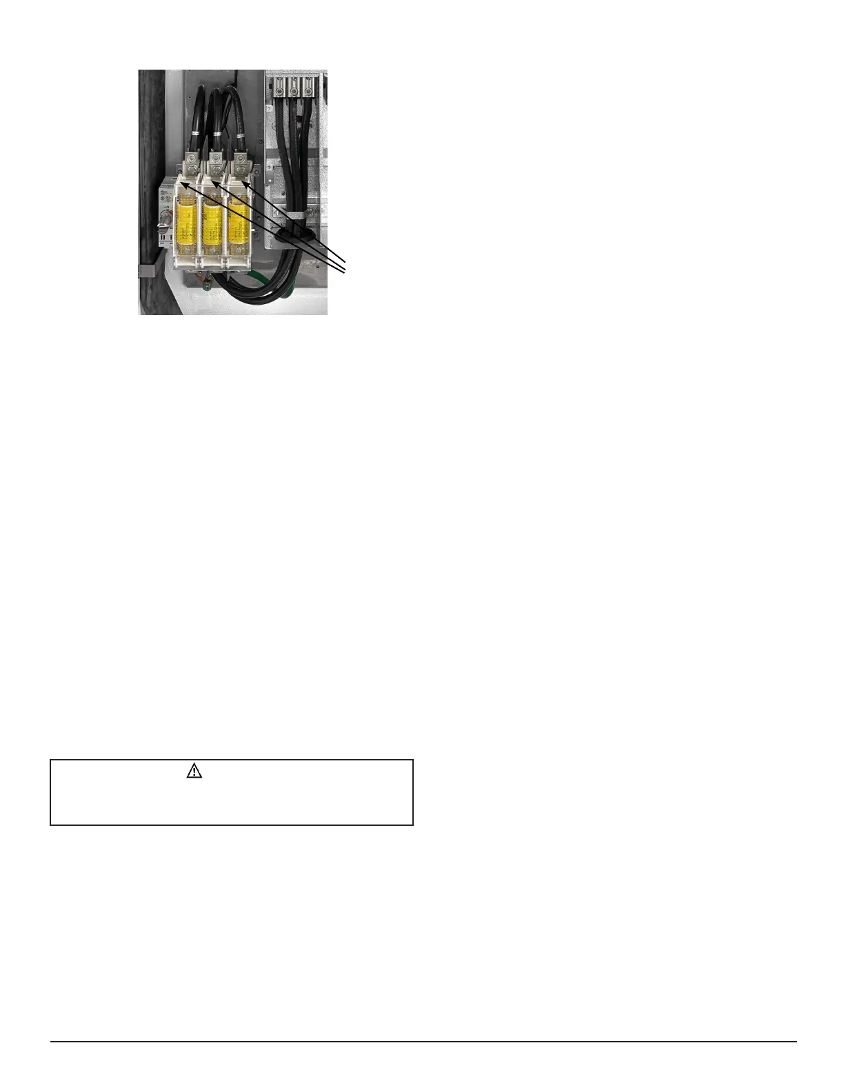
3.2 LINE FEED
This equipment is designed for line connection directly to the integral
disconnect switch. Factory wiring transmits power to the variable
frequency drive.
1. Size line wiring according to drive manufacturer’s specifications.
2. Attach line conductors with phase A on the left, B center and C to
the right (see torque table in Section 5.3).
3.3 LOAD FEED AND SHIELD GROUNDING TO
DRIVE
This equipment is designed for load connection directly from the variable
frequency drive, although, in the case of an oversized VFD for the given
motor, use the VFD and motor manufacturer’s recommendations for
proper motor overload protection. In certain cases, it is required to
include additional motor overload protection between the VFD and the
motor for proper motor overload protection. Always be sure to shield
load wiring from line and control wiring to reduce noise. Refer to the
drive manufacturer’s manual for further details.
1. Attach load conductors with phase A to U, B to V, and C to W (see
torque table in Section 5.3).
2. Attach motor cable shielding to VFD ground (see recommendations
by drive manufacturer).
3. Refer to the drive manufacturer’s manual for further information
regarding drive installation.
3.4 CONTROL WIRE ROUTING
To avoid the transmission of noise to/from the blower, control system
and/or the variable frequency drive load conductors, be sure to bundle all
field control wiring and shield as necessary.
Disconnect
Terminals
CAUTION
Failure to add additional motor overload protection between the VFD
and motor when required can cause motor failure and equipment
damage.
 Loading...