IF 1767 • 09/15 Copyright
©
2015, Eaton’s Crouse-Hinds Division Page 11
8. REPLACEMENT PARTS
ACE Series systems are designed to provide years of reliable service.
However, should the need for replacement parts arise, they are avail-
able through your Eaton’s Crouse-Hinds Division Distributor. Assistance
may also be obtained through your Sales Representative or the Eaton’s
Crouse-Hinds Division Customer Service Department.
8.1 PRE-FILTER KIT
ACE KIT1: Pre-Filter and Hardware (1 pc.)
8.1.1 PRE-FILTER INSTALLATION INSTRUCTIONS
1. Remove rubber caps from explosionproof filters.
2. Install wire guard using the bracket, screw and lock washer provided
to the bottom filter(s).
3. Align guard with notches within the bracket as shown.
4. Tighten screw.
5. Slip pre-filter mesh over guard.
6. Be sure to stretch pre-filter elastic band completely around the
explosionproof filter and seat the elastic band on the filter’s threads.
This will ensure all air flow to the bottom filters passes through the
pre-filters.
8.2 SINTERED FILTER KIT
ACE KIT2: Filter Assembly (1 pc.)
8.2.1 SINTERED FILTER INSTALLATION
INSTRUCTIONS
1. Remove shroud and pre-filters and place all parts in a secure area.
2. Using a 1” socket wrench, remove all filters from the enclosure (top
and bottom).
3. Remove rubber caps from explosionproof filters.
4. Apply thread grease to threads of explosionproof filters.
5. Install new filters (top and bottom) and torque each to 133 ft.-lbs.
(180 N-m).
6. Install pre-filters and shrouds; refer to Sections 2.6 and 2.7.
8.3 BLOWER KIT
ACE KIT3: Blower, Manifold and Hardware (1 pc.)
8.3.1 BLOWER INSTALLATION INSTRUCTIONS
1. Disconnect blower power, ground and control leads from fuse
blocks (refer to wiring diagrams in Section 3.5).
2. Loosen five (5) nuts holding blower bracket and baffle to mounting
plate. DO NOT remove.
3. Loosen and remove manifold clamp bracket nuts and lock washers.
DO NOT remove jam nuts positioned behind the manifold clamp
bracket.
4. Remove blower and brackets.
5. Remove manifold and manifold clamp bracket.
6. Remove blower cooling intake and hose clamp from old blower
assembly and hold for re-assembly.
7. Loosen and remove three (3) screws and washers holding the baffle
to the blower bracket. Remove baffle and hold for re-assembly.
8. Attach baffle to new blower bracket using the same three (3)
screws and washers.
9. Align new manifold to enclosure wall.
10. Align new manifold clamp bracket to threaded studs. Be sure the
manifold clamp bracket flanges point toward the interior of the
enclosure.
11. Install four (4) lock washers and nuts on threaded studs hand tight
before applying required torque. Tighten to 20 in.-lbs. DO NOT
overtighten.
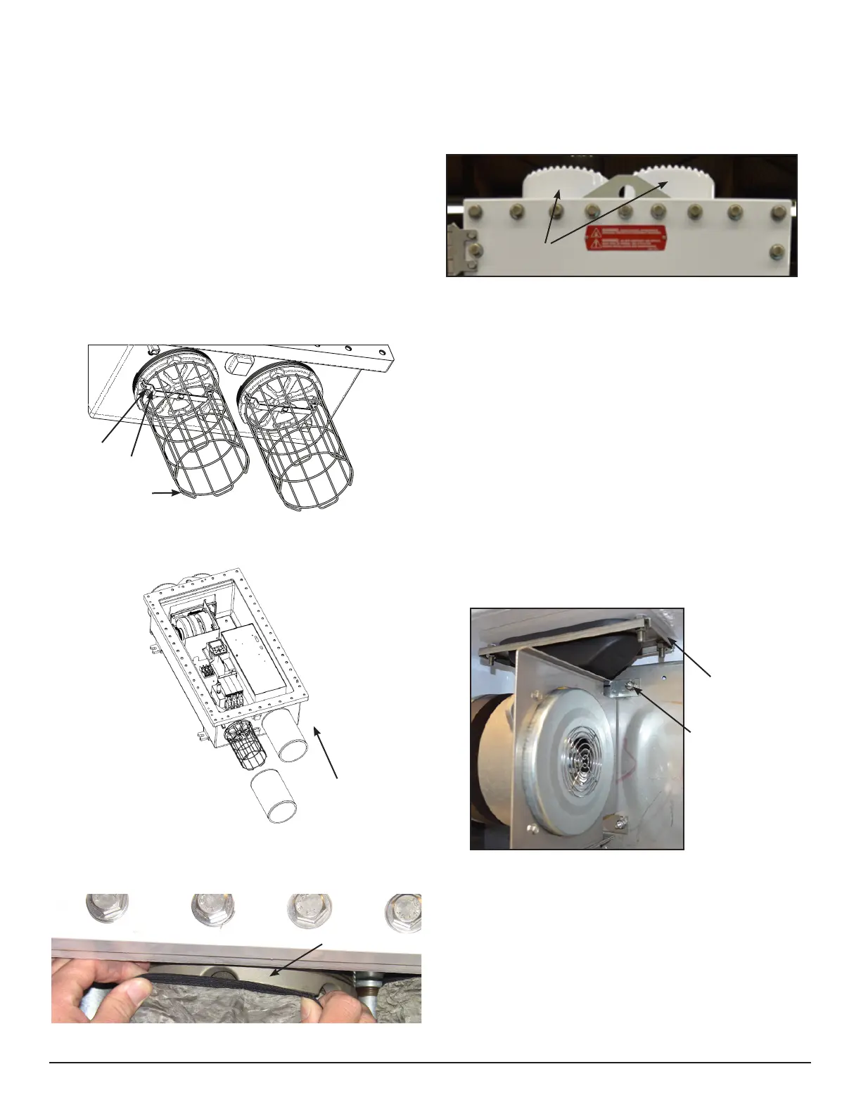
Explosionproof
Filter
Filter
Shrouds
Manifold Clamp
Bracket
Loosen and DO NOT
remove nut during
replacement
Detail View
Notch
Bracket
Guard
 Loading...