12. Slide new blower/bracket assembly into place until fully seated,
aligning to the threaded studs and the manifold.
13. Tighten nuts wrench tight.
14. Tighten manifold hose clamp, while compressing the manifold to
the blower, to 20 in.-lbs.
15. Re-attach blower cooling intake and tighten hose clamp to 20
in-lbs. Be sure to align bottom of blower cooling intake to the
explosionproof filter at the bottom of the enclosure.
16. Terminate the blower power wires to the appropriate fuse block
connections (refer to wiring diagrams in Section 3.5).
17. Perform a continuity check between each blower power terminal
and each phase of the integral disconnect switch.
18. Terminate the blower control wires to the appropriate terminal block
connections (refer to wiring diagrams in Section 3.5).
19. Perform a continuity check between each blower control terminal
and the RO3 relay terminals on the drive (refer to wiring diagrams in
Section 3.5).
20. Terminate the blower ground wire to the appropriate nearest ¼-20
stud and secure connection (refer to wiring diagrams in Section 3.5).
21. Perform a continuity check between the ground terminal and the
ground lug adjacent to the integral disconnect switch.
8.4 WINDOW KIT
• ACE KIT7 (ENCLOSURE SIZES 1 AND 2): 3/8” Window, Bracket,
Hardware, and IF1706 (1 pc.)
• ACE KIT8 (ENCLOSURE SIZE 3): 5/8” Window, Bracket, Hardware,
and IF1706 (1 pc.)
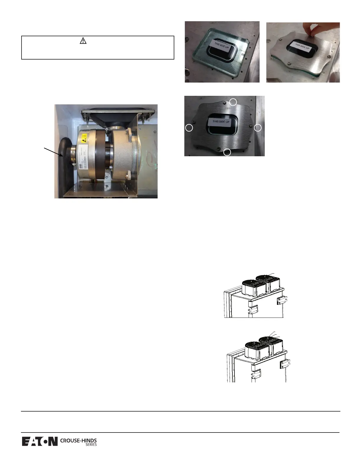
8.4.1 WINDOW KIT INSTALLATION
INSTRUCTIONS
1. Wipe down glass window with cleaner.
2. Place glass over milled pocket of cover as shown in image 1 and
exploded view drawing below.
3. Place bracket over glass and attach with 4 x #10-24 screws and 4 x
#10 lock washers as shown in image 2 and exploded view drawing
below.
4. Hand tighten screws first in pattern shown on image 3 below, then
torque screws to 23 in.lbs. in approximately 5 in.lb. increments
following the same sequence.
5. Shim Gage window with .0015 Shim Stock to check that it is sealed.
8.5 CAST FILTER SHROUD REPLACEMENT KIT
ACE KIT 9: Cast shroud and hardware (1 pc.)
8.5.1 FILTER SHROUD INSTALLATION
INSTRUCTIONS
1. Remove rubber caps from explosionproof filters.
2. Insert threaded rods into the explosionproof filters. Leave 3-
5
⁄8 of
threaded rod exposed.
3. Place shroud over explosionproof filters and threaded rod, with
shroud opening facing back of enclosure. See Figure 2.
4. Insert washer and nuts onto end of threaded rod and tighten
securely until shroud is firmly contacting the top wall of the
enclosure. See Figure 3.
CAUTION
To avoid system malfunction and electrical shock, be sure that all
wires are aligned in the baffle’s wire pass through.
Blower
Cooling
Intake
Image 1 Image 2
Image 3
1
2
3
4
ACORN NUT
LOCKING NUT
WASHER
Figure 3
Figure 2
All statements, technical information and recommendations contained herein are based on information and tests we believe to be reliable. The accuracy or
completeness thereof are not guaranteed. In accordance with Eaton’s Crouse-Hinds Division’s “Terms and Conditions of Sale,” and since conditions of use are
outside our control, the purchaser should determine the suitability of the product for his intended use and assumes all risk and liability whatsoever in connection
therewith.
Eaton’s Crouse-Hinds Division IF 1767
1201 Wolf Street, Syracuse, New York 13208 • U.S.A. Revision 1
Copyright
©
2015 Revised 09/15
 Loading...