22
Series NRX Low Voltage Power (Air)
Circuit Breakers User Manual
EATON CORPORATION www.eaton.com
Instructional Book MN01301003E
Effective July 2011
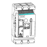
Rating plug
Series NRX circuit breaker trip units use a fixed type rating plug. The
current rating of the rating plug must be equal to or less than the
current rating as established by the frame rating module and the breaker
maximum rated current (Iu) as listed on the name plate in (Figure 1).
If the circuit breaker is carrying current and the rating plug is removed,
a trip will occur. Make certain the rating plug is secured in position.
Current sensors
Three Rogowski coil type current sensors are installed on the load
terminals at the bottom rear of the circuit breaker. The sensors furnish
the trip unit with a signal and the energy required to trip the circuit
breaker.
A neutral current sensor is available for customer installation, and must
be ordered separately.
Frame rating module
The frame rating module is a device used to establish the maximum
RMS current that can be continuously carried. The frame rating
module, mounted just below the trip unit, also acts as a mechanical
means to reject the insertion of a rating plug with an unacceptable
current rating (Figure 6).
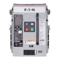
Trip actuator
The low-energy trip actuator is a small electromagnetic device that
provides the necessary mechanical force to initiate the tripping action
of the circuit breaker. The electronic trip unit provides a pulse to the
coil of the trip actuator, allowing the mechanical tripping action to take
place. The trip actuator is reset by the operating mechanism.
Fixed high instantaneous non-adjustable trip
Series NRX circuit breakers have a fixed instantaneous non-adjustable
setting. This fixed instantaneous trip will initiate a trip at a high current
peak which depends on the circuit breaker type and rating. This setting
is always active, regardless of the instantaneous setting.
Non-Automatic Circuit Breaker
Series NRX is available in a non-automatic configuration. It is derived
from the corresponding NRX automatic breaker but does not include
the Digitrip trip unit, Rogowski coil type current sensors, and the high
instantaneous trip feature. The overall dimensions and the capability
of mounting most accessory items are maintained. Non-automatic
breakers are tested in keeping with IEC 60947-2 requirements.
ST1
1
2
ST2
UV1
3
4
UV2
OT1C
5
6
OT1M
OT1B
7
8
OT2B
OT2C
9
10
OT2M
ALMC
11
12
ALM1
N1
15
16
N2
G1
17
18
G2
SGF2
19
20
SGF1
+24V
21
22
AGND
CMM1
23
24
CMM2
CMM3
25
26
CMM4
ZOUT
27
28
ZCOM
ARMS2
33
34
ARMS1
35
36
37
38
39
40
ARCON1
ARCON2
41
42
ARCON3
43
44
45
46
LN
ZIN
29
30 32
31
ALM2
13
14
47
48
SR1
49
50
SR2
EO1
51
52
EO2
SC
53
54
LCB
LCC
55
56
LCM
C1
57
58
A1
C2
61
62
A2
C3
63
64
A3
B3
65
66
B4
C4
67
68
A4
C5
69
70
A5
B5
71
72
B6
C6
73
74
A6
C8
79
80
A8
C9
81
82
A9
B9
83
84
B10
C10
85
86
A10
C11
87
88
A11
B11
89
90
B12
C12
91
92
A12
C7
75
76
A7
78
B8
77
B7
B2
B1
59
60
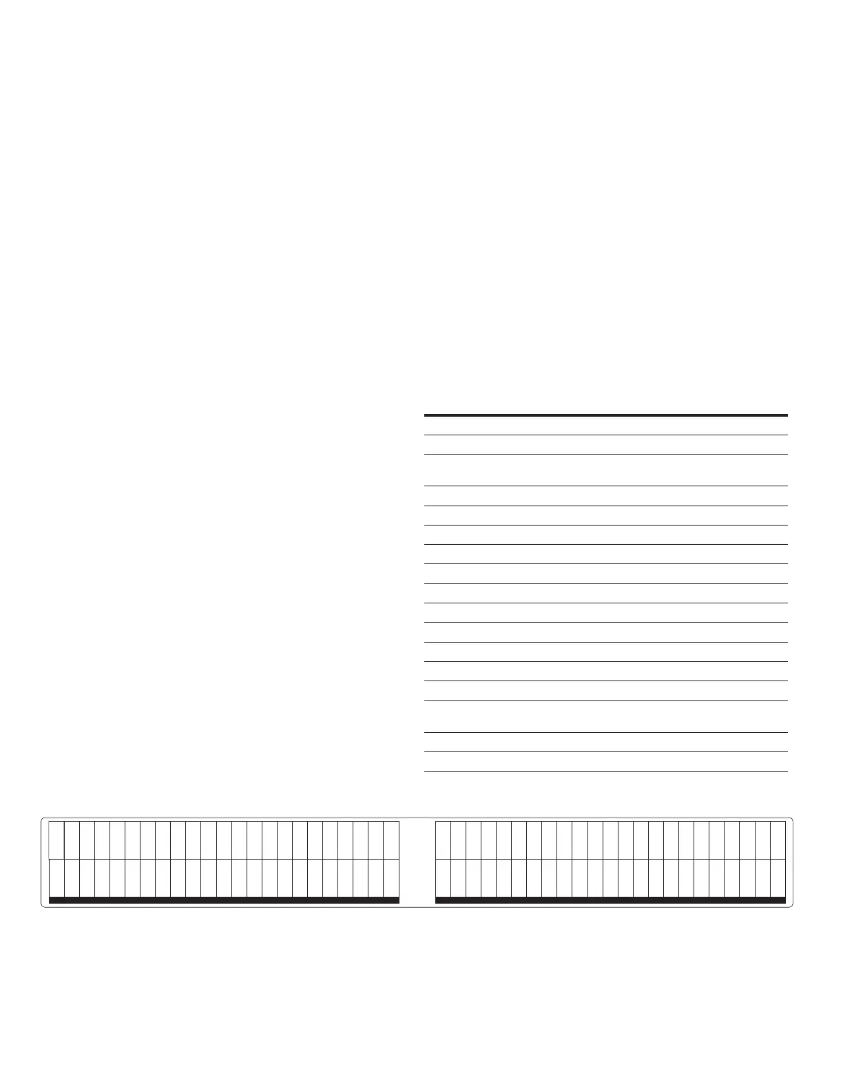
66B2595H01
(Left Side) (Right Side)
Figure 26. Secondary Point Identifications
Secondary contacts and connection diagrams
A maximum of 92 secondary wiring connection points are available,
each dedicated to a specific function. The number of secondary blocks
mounted depends on a number of considerations, such as whether
the circuit breaker is electrically or manually operated and how many
features are required. All necessary customer secondary connection
points are accessible without removing the breaker’s front cover. Each
connection point is permanently identified.
Customer secondary wiring contact points are identified on the
product (Figure 26). For a drawout breaker this marking is laser etched
into the Arc Hood of the drawout cassette (Figure 3). For a fixed
mount breaker this is a label applied to the top of the front cover of
the breaker (Figure 5).
The connection diagram and specific secondary contact information for
all Series NRX circuit breakers using Digitrip trip units can be found in
the Series NRX Wiring Diagram document TD01301014E.
Series NRX Wiring Index (TD01301014E)
Wiring Topic
Zone Interlock Wiring
Digitrip Alarm Wiring
Ground Fault Residual Three-Phase, Four-
Wire
Source Ground Fault Sensing
Zero Sequence Ground Fault Sensing
Maintenance Mode Wiring
INCOM Communications Module (ICAM)
Modbus Communications Module (MCAM)
PROFIBUS DP (PCAM)
Ethernet (ECAM)
Communications Control
Undervoltage Release
Circuit Breaker Control - Type NF Frame
Circuit Breaker Control - Type RF Frame
Series NRX NF Mounted Breaker (with
external PT Module)
Master Connection NF
Master Connection RF