28
Series NRX Low Voltage Power (Air)
Circuit Breakers User Manual
EATON CORPORATION www.eaton.com
Instructional Book MN01301003E
Effective July 2011
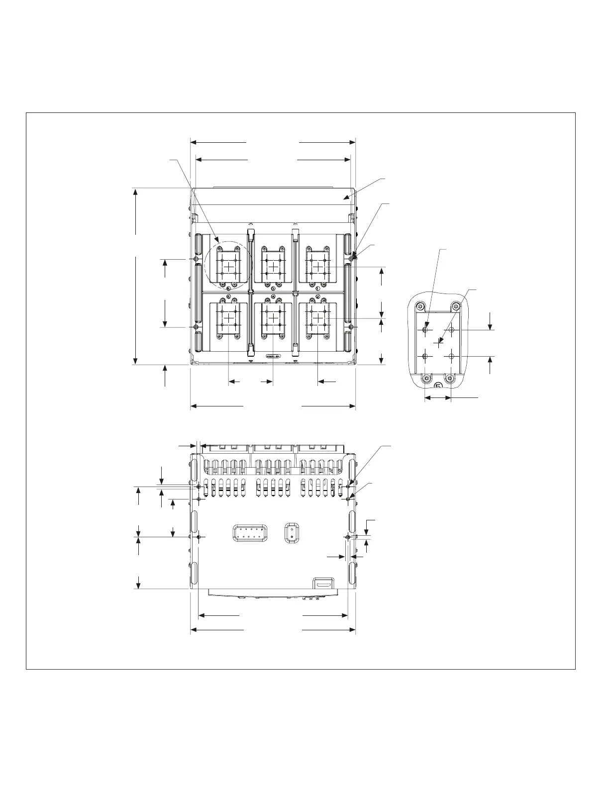
Section 5: Dimensional Drawings for Installation of Drawout Circuit Breaker and Cassette
16.77 (425,8)
15.72 (399,4)
ARC HOOD
SEE
DETAIL A
17.96
(456,2)
4X Ø.35 (9)
.35 (9)
.43 (11)
2X 6.90
(175,4)
4.53
(115)
2X 3.82
(97)
4.72
(119,9)
5.20
(132,1)
4X Ø.38
(9,6)
4.53
(115)
.43 (11)
16.77 (425,8)
.35 (9)
5.13
(103,2)
3.85
(97,8)
5.25
(133,4)
4X MOUNTING
LOCATIONS
OF HOLE
PATTERN
DETAIL A
Ø M8 X 1.25 TAPPED
0.35-IN MAX.
THREAD DEPTH FROM
COPPER SURFACE
3X 15.14 (384,6)
16.77 (425,8)
6x Mounting Holes
Must Use Reduced Head Height
Hardware at These Locations
1.34
(34)
1.34
(34)
Figure 32. Three-Pole Drawout Cassette—Rear/Bottom Views in Inches (mm)
 Loading...