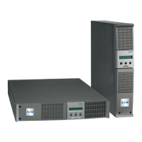
1.2 Rear Panels
Evolution S 2500 / S 3000
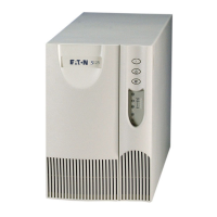
Evolution S 1250 / S 1750 / 2000
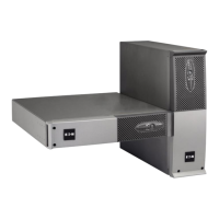
Evolution S EXB (optional battery module)
(12) Connectors for battery modules (to the UPS
or to the other battery modules)
(13) Connectors for automatic recognition of
battery modules
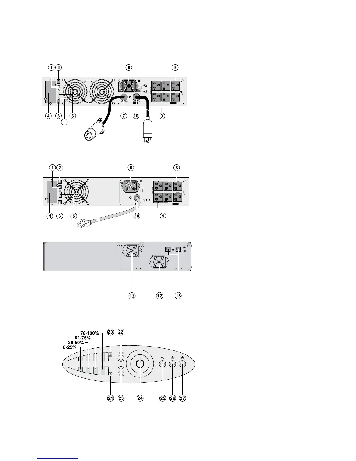
1.3 Control Panel
1. Presentation
86-81710-00EN A03 - Page 10
(20) Bargraph indicating the percent load
(21) Bargraph indicating battery charge level
(22) Programmable outlet 1 is supplied with
power
(23) Programmable outlet 2 is supplied with
power
(24) Lighted ON/OFF button for outlets
(25) Load protected LED
(26) Downgraded operation LED
(27) Load not protected LED
(1) USB communication port
(2) RS232 communication port
(3) Connector for automatic recognition of an
additional battery module
(4) Slot for optional communication card
(5) Connector for ROO (remote ON/OFF) or RPO
(Remote Power OFF) control
(6) Connector for additional battery module
(7) 30A outlet for connection of equipment (for
Evolution S 2500 and S 3000 only)
(8) A group of 2 programmable outlets for
connection of equipment
(9) Group of 4 outlets for connection of
equipment
(10) Attached 6 ft. input power cord for AC-power
source
L5-30P for S 2500/S 3000
5-15P for S 1250
5-20P for S 17500/2000
(a) LED indicating site wiring fault (SWF) alarm
with reset button
 Loading...