2.4 Communication Ports
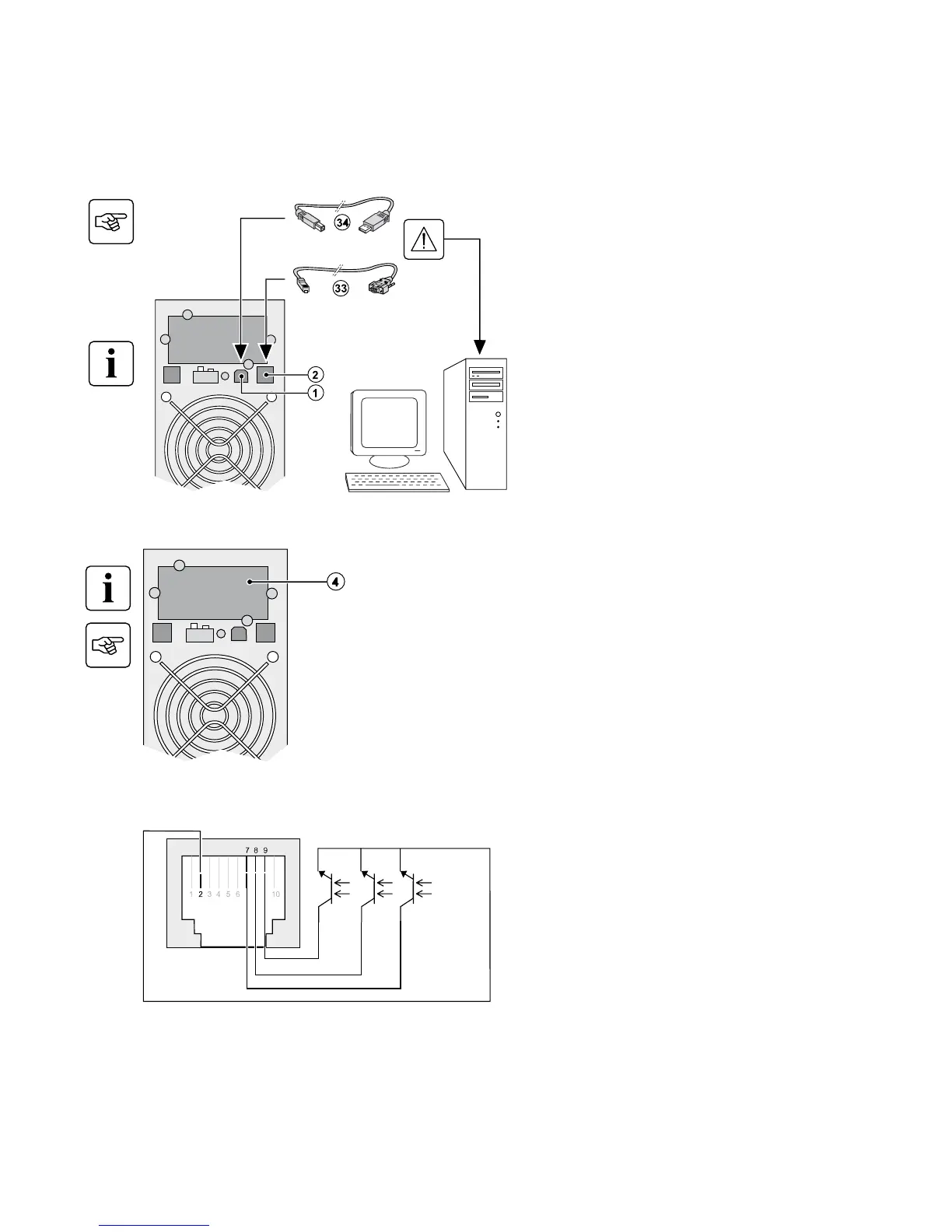
Connection of RS232 or USB communication port
The RS232 and USB communication ports cannot operate simultaneously.
Installation of the communication cards (optional)
Limited-access slot for the
communication card
Characteristics of the contact communication port (optional)
w Pins 1, 3, 4, 5, 6, 10: not used
w Pin 2: common (user)
w Pin 7: low battery
w Pin 8: operation on battery power
w Pin 9: UPS ON, equipment supplied
n.o.: normally open contact
When a signal is activated, the contact is closed between the common (pin 2) and the pin for the corresponding signal.
Contact characteristics (optocoupler)
w Voltage: 48 V DC max
w Current: 25 mA max
w Power: 1.2 W
2. Installation
86-81710-00EN A03 - Page 13
1. Connect the RS232 (33) or USB (34)
communication cable to the serial or USB port
on the computer equipment.
2. Connect the other end of the communication
cable (33) or (34) to the USB (1) or RS232 (2)
communication port on the UPS.
The UPS can now communicate with EATON
power management software.
It is not necessary to shutdown the UPS before
installing a communication card.
1. Remove the slot cover (4) secured by screws.
2. Insert the communication card in the slot.
3. Secure the card cover with the 2 screws.
 Loading...