SX1278 Wireless Module E32 Series User Manual
Copyright ©2012–2017, Chengdu Ebyte Electronic Technology Co., Ltd. 13 / 24
4. Recommended circuit diagram
The UART module is TTL level. Please connect to MCU of TTL level.
For some MCU works at 5VDC, it may need to add 4-10K pull-up resistor for the TXD & AUX pin.
4.1 Reset
When the module is powered, AUX outputs low level immediately, conducts hardware self-check and sets the
operating mode on the basis of the user parameters. During the process, the AUX keeps low level. After the process
completed, the AUX outputs high level and starts to work as per the operating mode combined by M1 and M0.
Therefore, the user needs to wait the AUX rising edge as the starting point of module’s normal work.
4.2 AUX description
AUX Pin can be used as indication for wireless send & receive buffer and self-check. It can indicate whether there are data that are
yet to send via wireless way, or whether all wireless data has been sent through UART, or whether the module is still in the process of
self-check initialization.
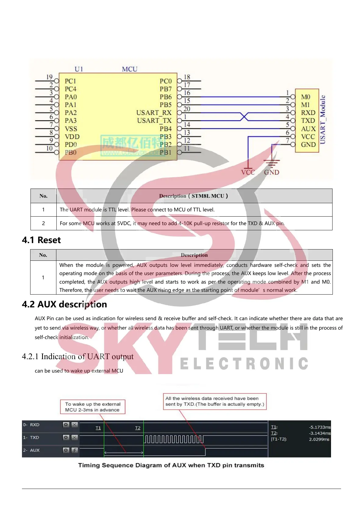
4.2.1 Indication of UART output
can be used to wake up external MCU
 Loading...