SX1278 Wireless Module E32 Series User Manual
Copyright ©2012–2017, Chengdu Ebyte Electronic Technology Co., Ltd. 6 / 24
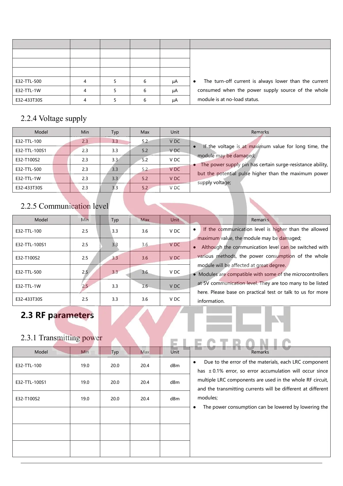
2.2.3 Turn-off current
● The turn-off current means the current consumed when
CPU, RAM, Clock and some registers remain operating
while SoC is at very low power consumption status.
● The turn-off current is always lower than the current
consumed when the power supply source of the whole
module is at no-load status.
2.2.4 Voltage supply
● If the voltage is at maximum value for long time, the
module may be damaged;
● The power supply pin has certain surge-resistance ability,
but the potential pulse higher than the maximum power
supply voltage;
2.2.5 Communication level
● If the communication level is higher than the allowed
maximum value, the module may be damaged;
● Although the communication level can be switched with
various methods, the power consumption of the whole
module will be affected at great degree.
● Modules are compatible with some of the microcontrollers
at 5V communication level. They are too many to be listed
here. Please base on practical test or talk to us for more
information.
2.3 RF parameters
2.3.1 Transmitting power
● Due to the error of the materials, each LRC component
has ± 0.1% error, so error accumulation will occur since
multiple LRC components are used in the whole RF circuit,
and the transmitting currents will be different at different
modules;
● The power consumption can be lowered by lowering the
transmitting power, but the efficiency of the internal PA will
be decreased by lowering transmitting power due to
various reasons;
● The transmitting power will be lowered by lowering the
power supply voltage.
 Loading...