Chengdu Ebyte Electronic Technology Co.,Ltd. E90-DTU(xxxSLxx-ETH)_V2.0 User Manual
Copyright ©2012–2023,Chengdu Ebyte Electronic Technology Co.,Ltd.
20
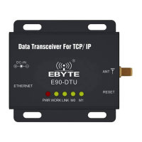
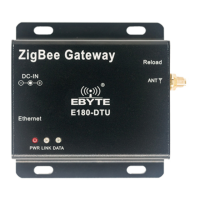
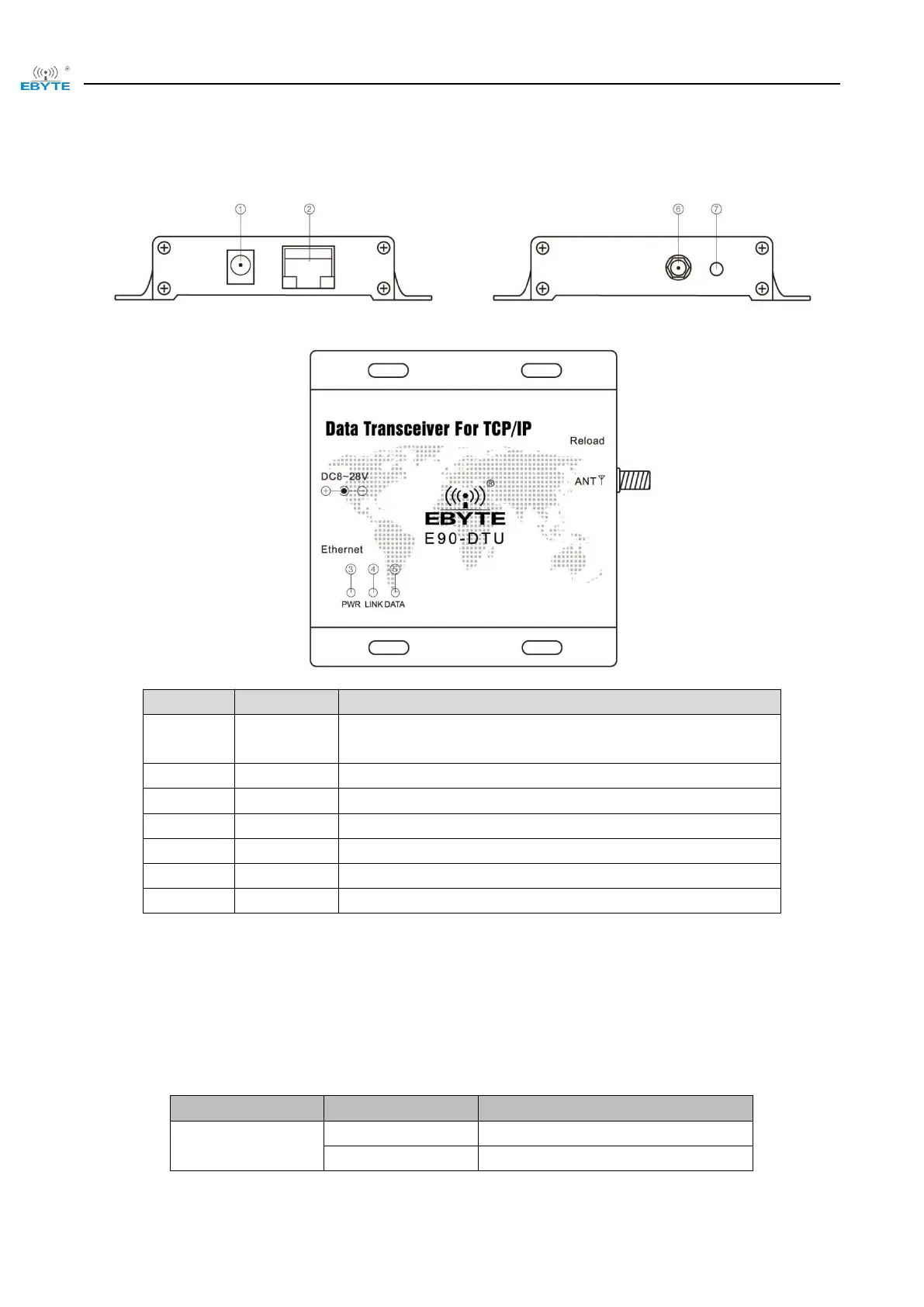
3.9 Pin definition
Power connector, 8 to 28V DC female connector (inner pin diameter
2.0mm, hole diameter 6.4mm)
Ethernet interface, standard RJ45 interface
Connection establishment indicator
Serial port send/receive indicator
SMA antenna connector (external screw, internal hole)
Restore to factory settings button
4 Basic function
4.1 Default parameter
40(230SL), 23(400SL), 18(900SL)
 Loading...