© Edwards Limited 2017. All rights reserved. Page 23
Edwards and the Edwards logo are trademarks of Edwards Limited.
Operation
A735-01-880 Issue C
4.3 Parallel control and monitoring
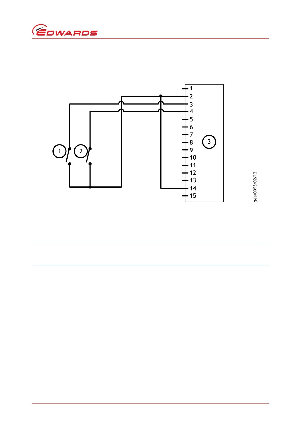
Figure 10 - Logic interface connections - parallel control
If using the normal and fail lines to drive the coils of d.c. relays, include a back EMF suppression diode in parallel
with each relay coil to protect the pump.
Connect the control equipment to the control input pins of the logic interface mating half. Refer to Table 11 to
identify the logic interface connector pins. The control inputs are as follows:
Start
Standby speed
Analogue speed
To activate any of these control inputs, connect the relevant control input (pin 14) to the 0 V control reference.
To monitor the normal status output, connect the control equipment to the Normal status output (pin 15) and to pin
2 of the logic interface mating half. The output can be used to control other devices in the pumping system. The
output can drive a low power relay of up to 24 V coil rating (up to 10 mA).
To monitor the fail status output, connect the control equipment to the fail output (pin 7) and to pin 2 of the logic
interface mating half. The output can be used to control other devices in the pumping system. The output can drive
a low power relay of up to 24 V coil rating (up to 10 mA).
1. Start switch
2. Standby switch (optional)
3. nXDS pump logic interface
 Loading...


