© Edwards Limited 2017. All rights reserved. Page 25
Edwards and the Edwards logo are trademarks of Edwards Limited.
Operation
A735-01-880 Issue C
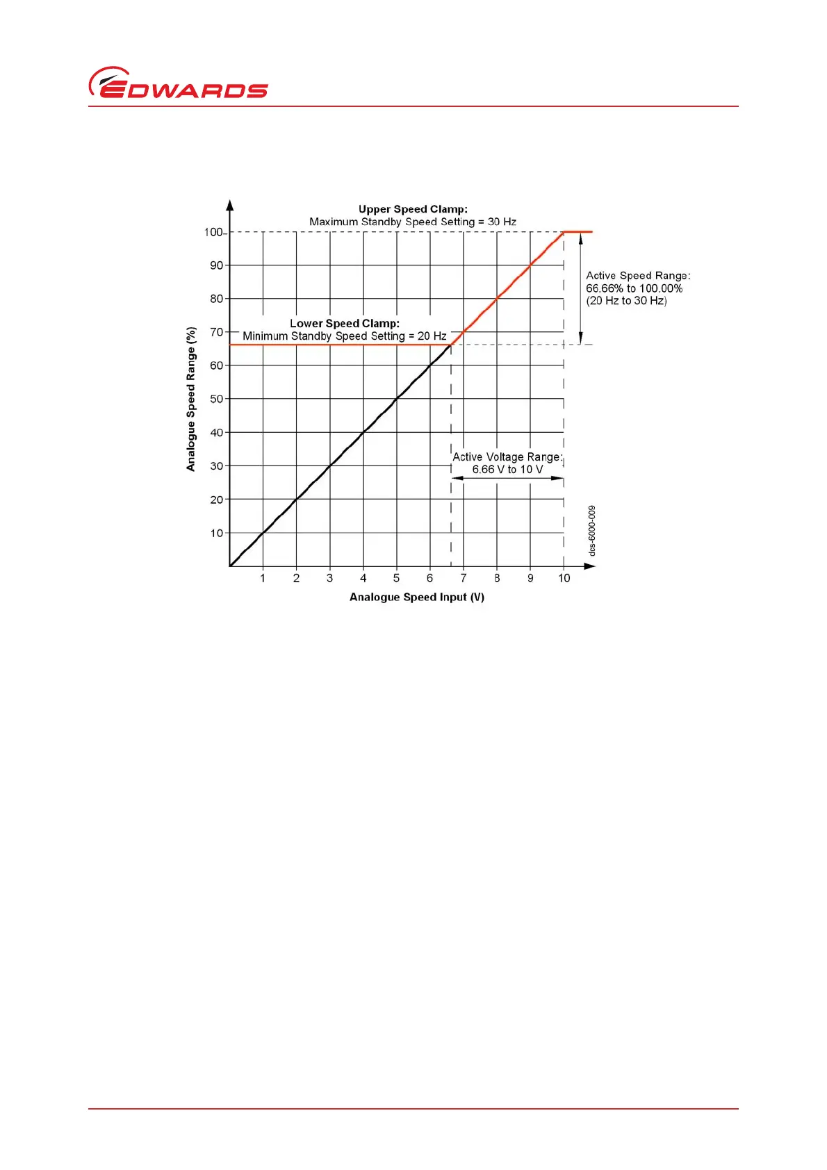
Figure 12 - Analogue speed control
Note: Voltages below 6.7 V will result in a clamped speed of 67% of full speed.
4.4.1 Hardware configuration
Using the 15-way D-type connector (Figure 1, item 7) apply the following signal configurations to enable the Analogue
Speed Control source (refer to Table 11):
Connect the Analogue Speed Enable control input (pin 1) to the 0 V Control Reference (pin 2).
Connect a suitably calibrated analogue voltage source (0 to +10 V), for example, (DAC) to the analogue speed control
input (pin 9). Alternatively connect the output of a potentiometer referenced to the pump reference voltage (pin 11)
to the analogue speed control input (pin 9). Refer to Figure 11. The 0 V rail of the external voltage source must be
connected to the 0 V Control Reference (pin 2) of the pump controller.
4.4.2 Operation
A +10 V input equates to a mechanical running speed which is equal to: 100% of the default run speed, that
is, 30 Hz.
The minimum running speed provided by the Analogue Speed control source, is clamped at the minimum
Standby Speed Setting, that is, approximately 67% of the default run speed of 20 Hz.
The maximum running speed provided by the Analogue Speed control source is clamped by the maximum
Standby Speed Setting, that is, 100% of the default run speed of 30 Hz.
 Loading...


