EasyManua.ls Logo

Electrolux Hob User Manual

Electrolux Hob
57 pages
To Next Page IconTo Next Page
To Previous Page IconTo Previous Page
Page #33 background image
SOI 04.05 FV 33/57 599 36 62-62
7. Light all the burners and adjust the flame setting to
minimum to check the stability of the flame (rapid
changing from a min to a max. and vice versa without
switching off the burner).
8. At the same time, check the appearance of the flame (no
smoke, yellow bits, no flame detachments).
If the flame is normal and stable, the "gas change"
procedure is complete.
However, if the flame is not stable when at minimum setting,
it is necessary to make the adjustments described below.
6.3 ADJUSTING THE MINIMUM SETTING
Proceed as follows to adjust the minimum setting correctly:
1. Carry out the operations described in "Adjusting the hob
for the type of gas", steps 1, 2, 3 and 4.
2. Touch the sensor key
to ignite the burner to be
adjusted.
The burner will automatically be set to the minimum
flame setting.
3. If the minimum flame is in fact too small, the burner will
go out. The hob automatically adjusts the minimum flame
setting and re-lights the burner.
4. With the burner lit, touch sensor keys
or make
fine adjustments until the flame is small and even around
the entire perimeter of the crown.
5. Touch the ON/OFF sensor
to switch off the hob.
NOTE :
If after adjusting the minimum setting, the flame is still
producing smoke, with yellow bits or possible flame
detachments, it is necessary to check the pressure and
eventually type and composition of the gas.
Fig. 31
Fig. 32
Fig. 33

Table of Contents

Question and Answer IconNeed help?

Do you have a question about the Electrolux Hob and is the answer not in the manual?

Electrolux Hob Specifications

General IconGeneral
BrandElectrolux
ModelHob
CategoryHob
LanguageEnglish

Summary

General Precautions for Electrolux Hobs

Introduction to the Service Manual

Manual Purpose and ESD Safety

Explains the manual's purpose and details ESD precautions for component handling.

Electronic Control System Overview

Provides an overview of the electronic control system and its features.

Technical Characteristics of Cooking Hobs

General Technical Data and Burner Specs

Lists technical data, burner types, nozzle markings, and gas delivery specifications.

Control Section and Burner Layout

Control Positions and Main Functions

Illustrates control layout and explains ON/OFF, burner, and timer controls.

Electronic Gas Control System

System Overview and Operation

Covers system overview, operation, and basic circuit diagrams.

System Components

Power Board and Sensor Boards

Details power board functions and sensor control interface circuit boards.

Flame Modulation and Safety Valves

Modulation Valves and Main Safety Valve

Explains powered flame modulation valves and the main safety solenoid valve.

Hob Component Layout

Internal Component Positions

Shows the internal layout and positions of all major components within the hob.

Operating the Hob

Touch Controls and Burner Ignition

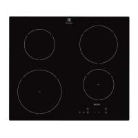
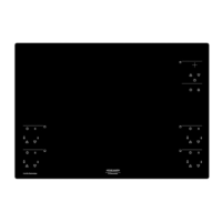
Explains touch controls, burner ignition, flame adjustment, and switching off.

Burner Operation and Safety Features

Covers switching off burners, failure to light, and automatic re-ignition.

Hob and Burner Automatic Switch-Off

Details automatic shutdown for burners and the entire hob.

Overheating Protection and Child Safety

Describes overheating protection and child safety feature activation.

Timer Functions

Programming Burner Switch-Off and Minute-Minder

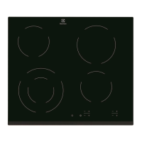
Guides on programming switch-off times and using the timer as a minute-minder.

Gas Type Adaptation

Replacing Nozzles and Adjusting Gas Type

Steps for replacing nozzles and adjusting the hob for different gas types.

Adjusting Minimum Flame Setting

How to adjust the minimum flame setting for optimal burner performance.

Error Codes

Trouble-Shooting

Troubleshooting with Error Codes

Guide to diagnosing faults using error codes and specific burner block issues.

Troubleshooting Without Error Codes

Troubleshooting steps for malfunctions not indicated by error codes.

Troubleshooting Interface Issues

Further troubleshooting for interface board connection and LED display issues.

Accessibility and Disassembly

Removing Hob Top and Gas Connection

Steps for removing the hob top, cabinet, and gas supply connection.

Removing Upper Glass Top

Instructions for removing the glass upper top of the hob.

Access to Component Zone

Dismounting Burner and Safety Valves

Steps to dismount burner control electric valves and the main safety electric valve.

Replacing Electronic Boards

Steps for replacing interface boards and the power board.

Replacing Burners and Thermocouples

Procedures for replacing burners and thermocouples.

Replacing Ignition Spark Plugs

Steps for replacing the ignition spark plugs.

Electric Diagrams

Basic Electric and Wiring Diagrams

Presents basic electrical schematic, wiring diagram, and key to diagrams.

Related product manuals