16
EMC Connectrix B Series DS-300B Hardware Reference Manual
Introducing the Connectrix DS-300B
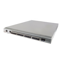
Port side of the DS-300B
Figure 1 shows the port side of the DS-300B.
All LEDs are on the port side of the switch; the nonport side is used to
allow the free flow of air. The DS-300B enclosure has forced-air
cooling, with the fans pushing the air from the nonport side of the
chassis through the enclosure, and exhausting to the port side.
For a complete description of the locations and interpretations of
these LEDs, refer to“Interpreting LED activity” on page 37 .
Figure 1 Port side of the DS-300B
1 System status (top) and power (bottom)
LEDS
4 USB port
2 System RS232 console port (RJ-45) 5 Fibre Channel status LEDs
3 Ethernet port with two Ethernet status
LEDs)
6 Fibre Channel Ports (24)
7 AC power receptacle
 Loading...