6 • Control Link ACC I&O Manual 026-4704 Rev 6
5 Wiring the
Control Link ACC
5.1. Power and Heater
Element Wiring
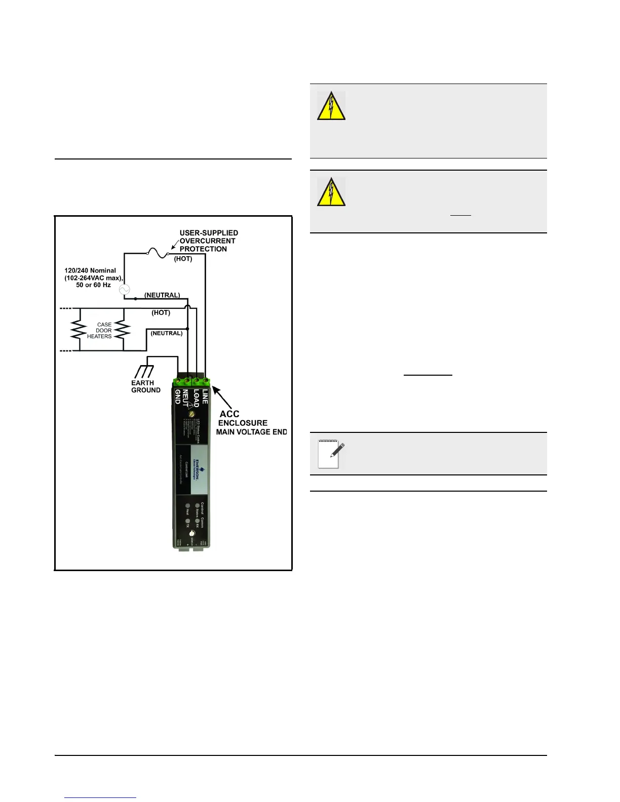
The screw connectors on the main voltage end of
the Control Link ACC enclosure are where the
connections to supply voltage and the case door
heater element(s) are made.
Connect the NEUT terminal to the NEUTRAL
side, and the LINE terminal to the HOT side of 120/
240 Nominal (102VAC to 264VAC), 50/60Hz line
voltage.
The LOAD terminal carries supply voltage when
the door heater Triac relay is ON (closed). Connect
the LOAD terminal and NEUTRAL side of the line
voltage to the case door heater elements. All heater
elements in the door frame and all doors of that frame
should be connected in parallel
to the Control Link
ACC.
Connect the GND terminal on the controller to
Ground.
5.2. Ratings and Current
Protection
The Control Link ACC (P/N 815-6100) is UL
Listed for up to 10A max (40°C) and 7A max (65°C).
The Control Link ACC (P/N 815-6105) is UL
Recognized, with external heat sink, for up to 30A
max (25°C), up to 26A max (40°C), and up to 18A
max (65°C).
Figure 5-1 - Power/Heater Wiring
WARNING! CONNECT THE LINE
VOLTAGE ONLY TO THE HIGH VOLTAGE
END OF THE ACC, WHICH CONTAINS A
NON-REMOVABLE 4-TERMINAL BLOCK.
OTHERWISE, DAMAGE TO THE BOARD MAY
RESULT.
WARNING! OVER-CURRENT
PROTECTION OF THE LOAD MUST BE
DONE OUTSIDE OF THE CONTROL LINK
ACC. THE ACC DOES NOT
HAVE
INTERNAL FUSING.
NOTE: For supply connectors, use 16AWG or
larger wires rated for at least 105 °C.

 Loading...