12 • Control Link ACC I&O Manual 026-4704 Rev 6
Controller Info setup screens:
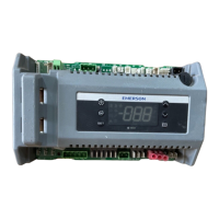
4. This screen will have a “Connection” field for all
COM ports on the E2. Highlight the COM port
connection field that will be used for Control Link,
and press - LOOK UP. From the list of
network types, select MODBUS.
5. Four fields will become visible underneath the
COM port connection field, which pertain to the
way the device communicates:
• Baud - Default setting is 19.2k. The baud rate
setting should be set to match the baud rate dip
switch settings of all Control Link devices. (All
devices connected to the same COM port should be
set to the same baud rate.)
• Data Size - Leave this field at the default value (8).
• Parity - Leave this field at the default value (None).
• Stop Bits - Leave this field at the default value (1).
6. Press
to save changes and exit.
7.2.2. Add and Connect Control Link
ACCs - E2 Firmware Revision
Prior to 2.8
To enable communications between E2 and the
Control Link units, the devices must be added and
addressed in E2.
1. Log in to the E2 with Level 4 access.
2. Press
- Connected I/O Boards
and Controllers.
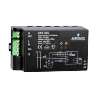
3. In the Connected I/O screen, in a section labeled
ECT Devices. Enter the number of ACC devices in
the CtrlLink ACC number field.
4. Press
to return to the Network Setup menu,
then select
- Controller Setup.
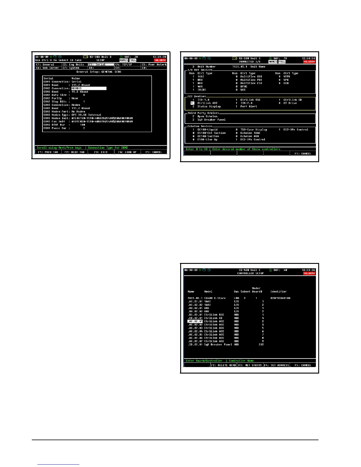
5. Locate the CtrlLink ACC units you added to the
network list (press
and to scroll through the
list). The default name for a Control Link ACC
begins with a two-letter designator of the model
type (AC for anti-condensate). If desired, enter a
new name for each device in the Name field.
6. By default, each CtrlLink ACC in the network list
has a board number of 0. To set the address and
begin communication, press
and select -
Select Address. In the list of MODBUS devices,
choose the address number corresponding to the
Figure 7-2 - Serial Communications Manager Screen
Figure 7-3 - Connected I/O Screen
Figure 7-4 - Controller Setup Screen

 Loading...