26
Application Engineering
BULLETIN
AE4-1383 R5
© 2012 Emerson Climate Technologies, Inc.
Printed in the U.S.A.
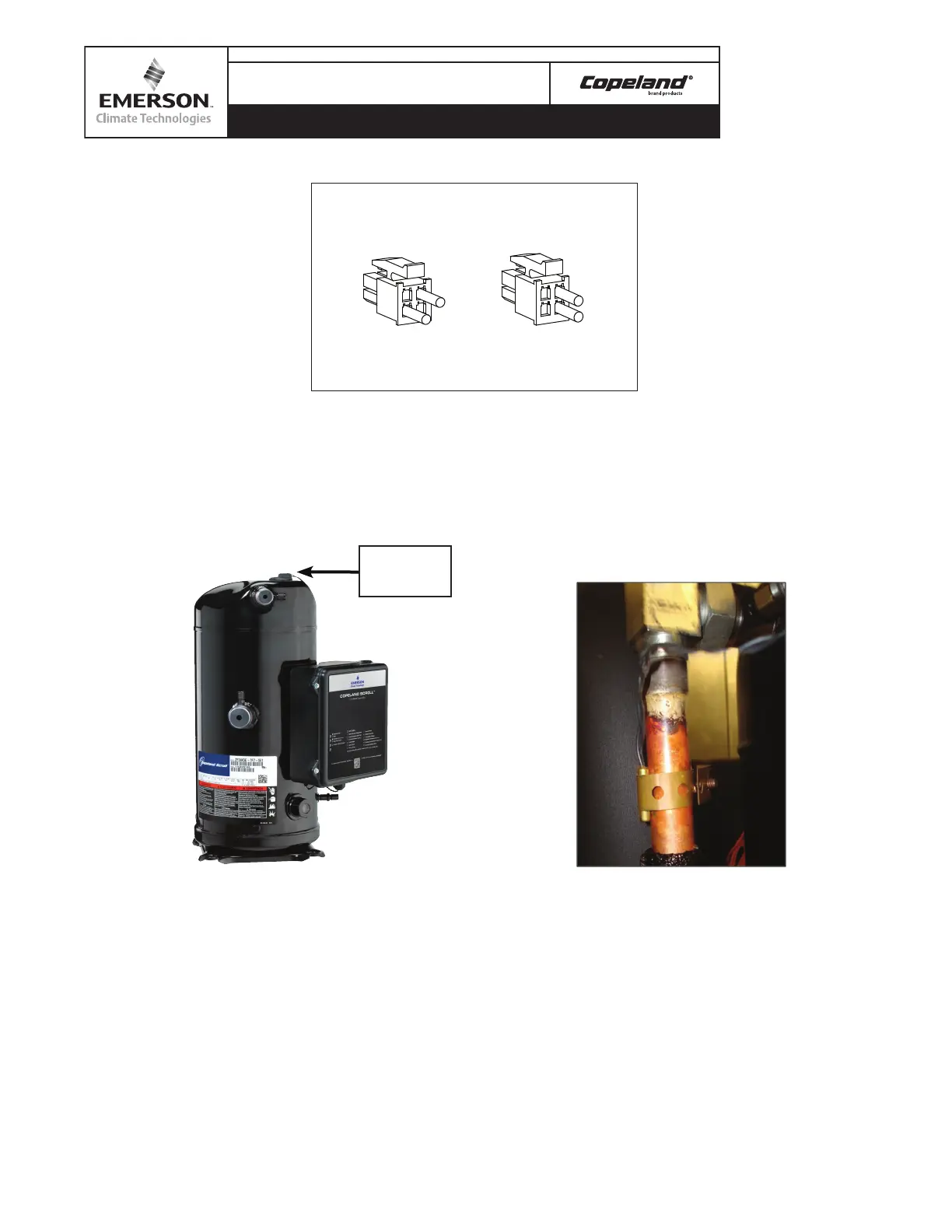
Figure 10 – Top Cap Thermistor
The top cap thermistor should be installed with di-
electric grease applied on the probe. When attaching
the probe to the compressor, a high temperature silicone
type sealant should be used not only to adhere the probe
to the compressor, but to also prevent any moisture from
entering the thermal well.
Figure 11 – Discharge Line Thermistor
The discharge line thermistor should be attached to
the discharge about 6 inches from the discharge of the
compressor.
Note! Although not depicted in this figure, the thermistor
should be well insulated to ensure accurate temperature
sensing.
Figure 9 – Discharge Thermistor Connector (Viewed from Wire Side)
Nominal Shutdown Temperature
Identification Tag Color
No Tag
Orange Tag
(130°C)
Top Cap
266°F
(117°C)
Line
242°F
Top Cap
Thermistor

 Loading...


