Instruction Manual
D102748X012
DLC3010 Digital Level Controller
Field Communicator Menu Tree
May 2018
109
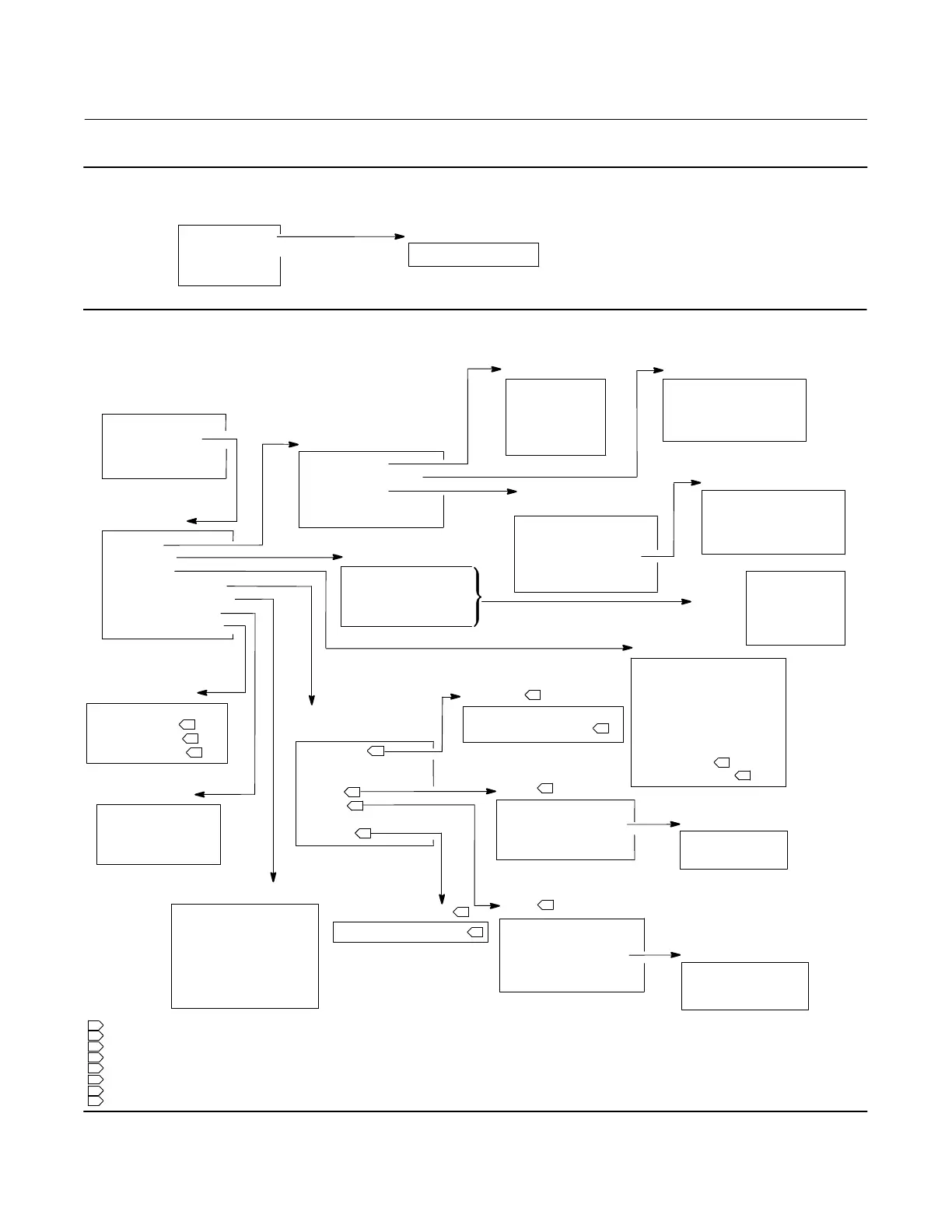
Figure B‐3. Configure > Guided Setup
Configure
1 Guided Setup
2 Manual Setup
3 Alert Setup
4 Calibration
Guided Setup
1 Instrument Setup
2‐1
2
Process Conditions
1 RTD Data
2
2 Proc Temp Source
3 Change Source
4 Fluid
4
4 Fluids
5
5 Temperature
6 Setting
6
Figure B‐4. Configure > Manual Setup
Sensor Units
1 Length
2 Volume
3 Weight
4 Torque Rate
5 Temperature
Manual Setup
1 Sensor
2 Variables
3 Ranging
4 Process Conditions
5 Device Identification
6 Communications
7 Instrument Display
2‐2‐1
Variables
1 Primary Variable
2 Change PV
3 Secondary Variable
4 Third Variable
Device Identification
1 Tag
2 Instr Serial Num
3 Sensor Serial Num
4 Final Assembly Num
5 Date
6 Description
7 Message
Sensor
1 Sensor Units
2 Sensor Dimensions
3 Torque Tube
4 Instrument Mounting
5 Sensor Damping
Sensor Dimensions
1 Displacer Length
2 Displacer Volume
3 Displacer Weight
4 Driver Rod Length
Torque Tube
1 TT Material
2 Change Material
3 Edit Compensation
4 Torque Rate
5 Change Torque Rate
2‐2‐1-1
2‐2‐1-2
2‐2‐1-3
Instrument Display
1 LCD Configuration
2 Display Mode
8
3 Change Mode
8
4 Decimal Places
8
2‐2‐7
Ranging
1 Upper Sensor Limit
2 Lower Sensor Limit
3 Minimum Span
4 Upper Range Value
5 Lower Range Value
6 Analog Output Action
7 Change Action
8 Level Offset
1
9 Set Level Offset
1
2‐2‐2
2‐2‐3
2‐2‐5
2‐2‐4
Configure
1 Guided Setup
2 Manual Setup
3 Alert Setup
4 Calibration
2‐2
2
Edit Compensation
1 TT Compensation
2 Torque Comp Plot
3 Pre-compensate
Torque Rate
2‐2‐1-3-3
RTD Data
2
1 Process Temperature
2 RTD Wire Resistance
3
Fluid
4
1 Lower Fluid Density
2 View/Edit SG Tables
3 Enter Constant SG
4 Measure SG
View/Edit SG Tables
1 Fluid Table
2 SG Comp Plot
Fluids
5
1 Upper Fluid Density
2 Lower Fluid Density
3 View/Edit SG Tables
4 Enter Constant SG
5 Load Steam Tables
View/Edit SG Tables
1 Upper Fluid Table
2 Lower Fluid Table
3 SG Comp Plot
Temperature Setting
6
1 Process Temperature
7
Communications
1 Polling Address
2 Burst Mode
3 Burst Option
4 Scan Device
2‐2‐6
2‐2‐4-1
2‐2‐4-4
2‐2‐4-5
2‐2‐4-4
2‐2‐4-4-2
2‐2‐4-4-3
NOTES:
1 ABSENT IN LIQUID DENSITY MODE
2 WHEN PROCESS TEMPERATURE SOURCE IS NOT MANUAL ENTRY
3 APPEARS ONLY IF TEMPERATURE SOURCE IS TWO-WIRE RTD
4 N LIQUID LEVEL MODE ONLY
5 IN INTERFACE LEVEL MODE ONLY
6 WHEN PROCESS TEMPERATURE SOURCE IS MANUAL ENTRY
7 EDITABLE IF TEMPERATURE SOURCE IS MANUAL ENTRY
8 ABSENT WHEN LCD IS NOT INSTALLED
1 PV
1 SV
1 TV
2 Units
3 Damping
2-2-2-1
2-2-2-3
2-2-2-4

 Loading...


