Instruction Manual
D103785X012
Configuration
June 2017
19
Section 3 Configuration
Guided Setup
Field Communicator Configure > Guided Setup (2‐1)
The following procedures will guide you through the instrument setup process.
D Device Setup—This procedure is used to configure actuator and valve information, calibrate the valve assembly, and
assign the tuning set for the valve assembly.
D Performance Tuner (instrument level AD, PD, ODV)—This procedure executes a simple step response test and then
calculates a recommended set of gain values based on the response of the control valve. See page 30 for additional
information.
D Stabilize Optimize (instrument level HC)—This procedure permits you to adjust valve response by changing the
digital valve controller tuning. See page 30 for additional information.
Manual Setup33
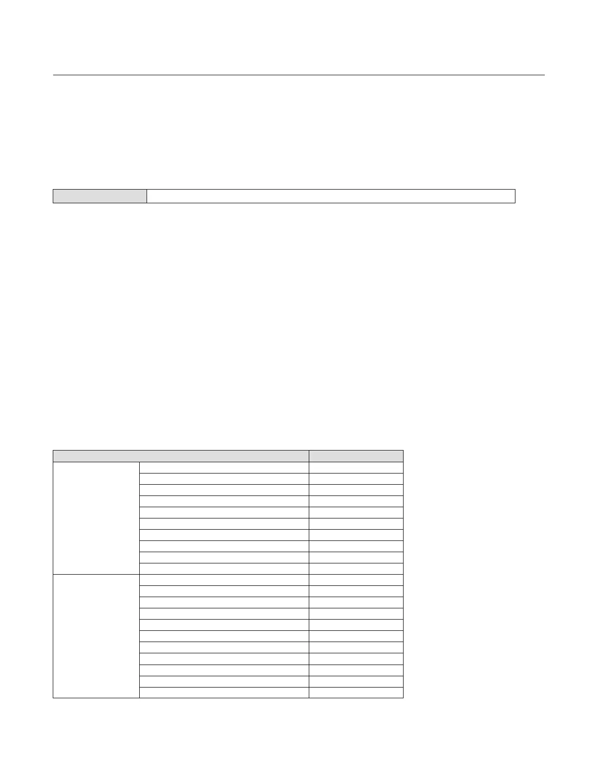
Manual Setup allows you to configure the digital valve controller to your application. Table 3‐1 lists the default settings
for a standard factory configuration. You can adjust actuator response, set the various modes, alerts, ranges, travel
cutoffs and limits. You can also restart the instrument and set the protection.
Table 3‐1. Default Detailed Setup Parameters
Setup Parameter Default Setting
(1)
Instrument
Configuration
Control Mode Analog
Restart Control Mode Resume Last
Analog In Range Low 4 mA
Analog In Range High 20 mA
Analog Input Units mA
Local AutoCal Button Disabled
Polling Address 0
Burst Mode Enable No
Burst Command 3
Cmd 3 (Trending) Pressure A-B
Dynamic Response and
Tuning
Input Characterization Linear
Travel Limit High 125%
Travel Limit Low -25%
Travel/Pressure Cutoff High 99.46%
Travel/Pressure Cutoff Low 0.50%
Set Point Rate Open 0%/sec
Set Point Rate Close 0%/sec
Set Point Filter Time (Lag Time) 0 sec
Integrator Enable Yes
Integral Gain 9.4 repeats/minute
Integral Deadzone 0.26%
-continued on next page-

 Loading...


