Instruction Manual
D103785X012
Configuration
June 2017
32
D Integrator Limit—The Integrator Limit provides an upper limit to the integrator output. The high limit is configurable
from 0 to 100% of the I/P drive signal.
Valve and Actuator
Field Communicator Configure > Manual Setup > Valve and Actuator (2‐2‐5)
Valve Style—Enter the valve style, rotary or sliding‐stem
Actuator Style—Enter the actuator style, spring and diaphragm, piston double‐acting without spring, piston
single‐acting with spring, or piston double‐acting with spring.
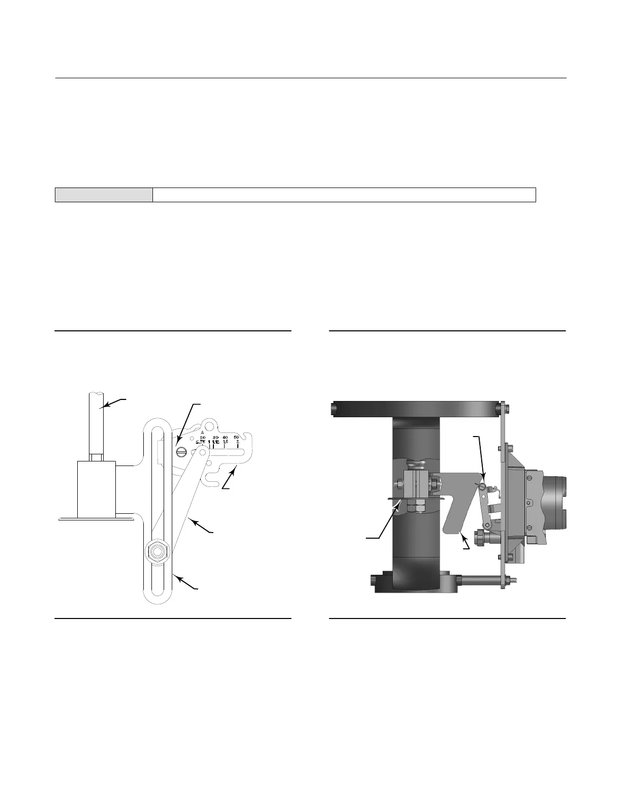
View/Edit Feedback Connection—Select Rotary All, SStem - Roller or SStem - Standard. For rotary valves, enter Rotary -
All, SStem - Roller. For sliding-stem valves, if the feedback linkage consists of a connector arm, adjustment arm, and
feedback arm (similar to figure 3‐3), enter SStem - Standard. If the feedback linkage consists of a roller that follows a
cam (similar to figure 3‐4), enter Rotary All, SStem - Roller.
Figure 3‐3. Feedback Connection for Typical
Sliding-Stem Actuator (Up to 4 inch Travel)
ACTUATOR
STEM
TRAVEL SENSOR SHAFT
FEEDBACK
ARM
CONNECTOR
ARM
ADJUSTMENT
ARM
Figure 3‐4. Feedback Connection for Typical
Long-Stroke Sliding-Stem Actuator (4 to 24 Inches
Travel)
CAM
ROLLER
STEM
CONNECTOR
X0914
Relay Type—There are three categories of relays that result in combinations from which to select.
Relay Type: The relay type is printed on the label affixed to the relay body.
A = double‐acting or single‐acting
B = single‐acting, reverse
C= single‐acting, direct
Special App: This is used in single‐acting applications where the “unused” output port is configured to read the
pressure downstream of a solenoid valve.
Lo Bleed: The label affixed to the relay body indicates whether it is a low bleed version.

 Loading...


