Quick Start Guide
D103556X012
DVC6200 Digital Valve Controllers
July 2017
24
FOUNDATION fieldbus or PROFIBUS PA Devices
Refer to the DVC6200f or DVC6200p instruction manual, available at Fisher.com or from your local Emerson sales
office for additional information.
The digital valve controller is normally powered over the bus from a power supply. Refer to the F
OUNDATION Fieldbus or
PROFIBUS site planning guide, available from your Emerson Automation Solutions sales office, for proper wire types,
termination, length, grounding practices, etc.
Note
To avoid the valve going to an unknown position when power is applied, the unit digital valve controller is shipped from the factory
with the transducer block mode Out of Service.
Wire the digital valve controller as follows, refer to figure 19.
1. Remove the wiring terminal box cap.
2. Bring the field wiring into the terminal box. When applicable, install conduit using local and national electrical codes
which apply to the application.
3. The instrument is not polarity sensitive. Connect one wire from the controller output to one of the LOOP screw
terminals in the terminal box shown in figure 19. Connect the other wire from the controller output to the other
LOOP screw terminal in the terminal box.
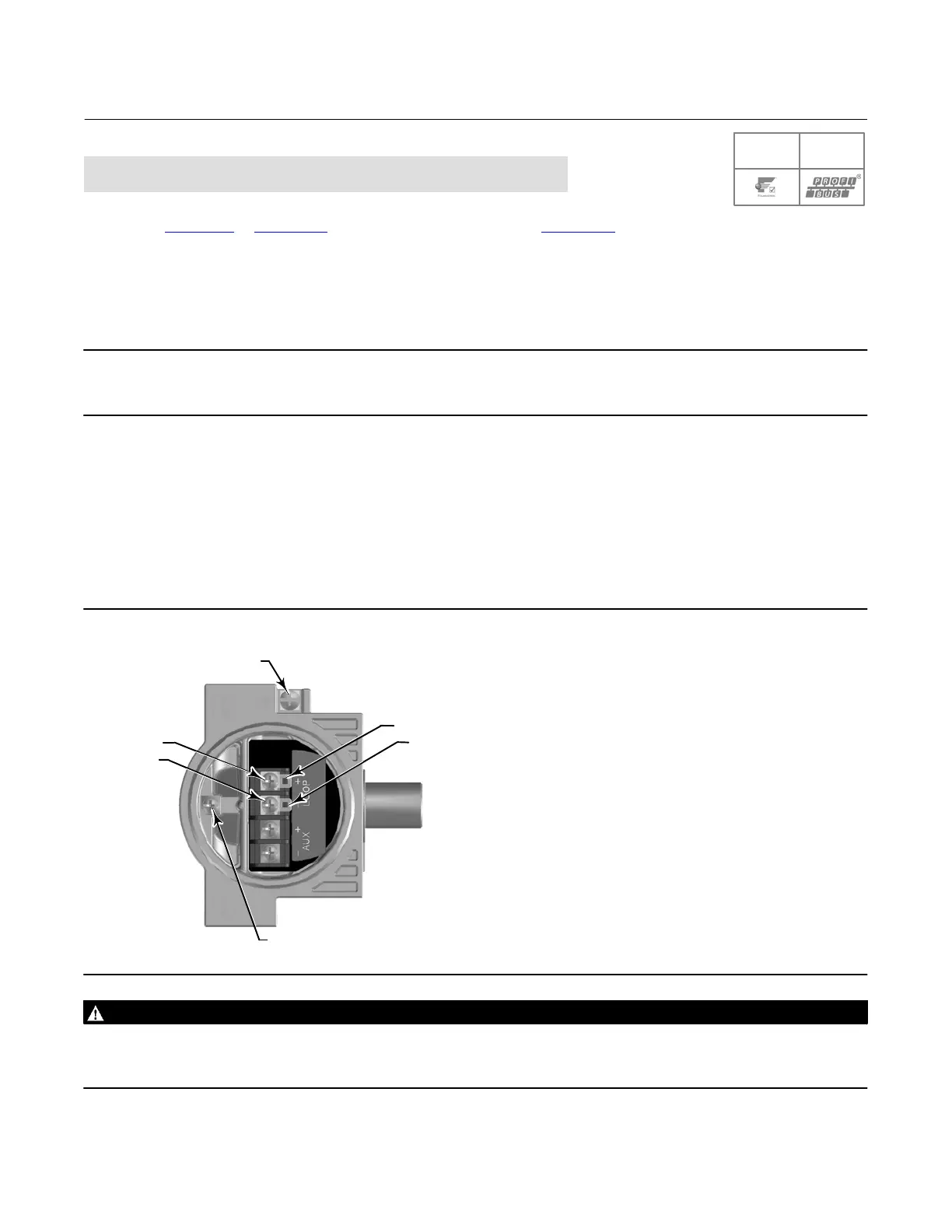
Figure 19. Loop Connections Terminal Box
EARTH
GROUND
TALK -
TALK +
SAFETY
GROUND
LOOP +
LOOP -
X0438
WARNING
Personal injury or property damage can result from the discharge of static electricity. Connect a 14 AWG (2.08 mm
2
)
ground strap between the digital valve controller and earth ground when flammable or hazardous gases are present. Refer
to national and local codes and standards for grounding requirements.

 Loading...


