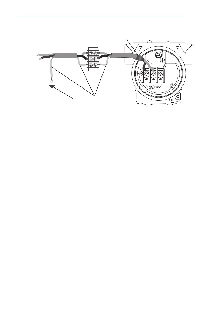
Figure 2-10: Wiring
A. Insulate shield and shield drain wire.
B. Insulate exposed shield drain wire.
C. Connect shield back to the power supply ground.
2.3 Grounding for transient terminal block
Ground termination is provided on the outside of the electronics housing and
inside the terminal compartment. These grounds are used when the transient
protection terminal blocks are installed. It is recommended that 18 AWG or
larger wire is used to connect housing ground to earth ground (internal or
external).
If the transmitter is currently not wired for power up and communication,
follow Connect the wiring and power up through step 7. When the
transmitter is properly wired, refer to Figure 2-10 for internal and external
transient grounding locations.
2.4
Verifying configuration
Verify the configuration using any HART capable configuration tool.
Configuration instructions for a Field Communicator are included in this step.
See Rosemount 3051 Reference Manual for configuration instructions using
AMS Device Manager.
2.4.1 Verifying configuration with a Field Communicator
A Rosemount 3051 DD must be installed on the Field Communicator to verify
configuration. Fast Key sequences for the latest DD are shown in Table 2-2.
For Fast Key sequences using legacy DD's, contact your local Emerson
representative.
Quick Start Guide February 2019
14 Emerson.com/Rosemount

 Loading...