4. Torque the bolts to the final torque value using the same crossing
pattern. See Table 2-1 for final torque value.
5. Verify that the flange bolts are protruding through the isolator plate
before applying pressure.
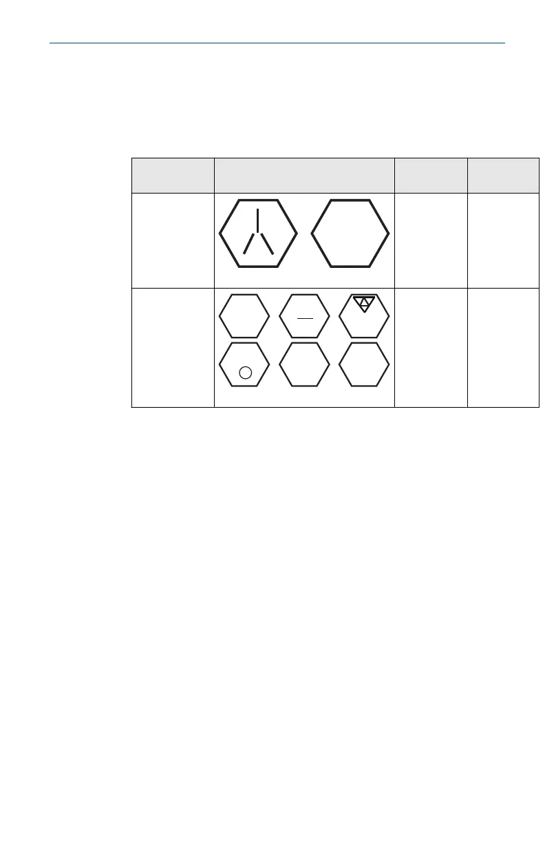
Table 2-1: Torque Values for the Flange and Flange Adapter Bolts
Bolt material Head markings Initial
torque
Final torque
CS
300 in-lb
650 in-lb
SST
150 in-lb 300 in-lb
2.1.5 In-line gage transmitter orientation
The low side pressure port (atmospheric reference) on the in-line gage
transmitter is located in the neck of the transmitter, behind the housing. The
vent path is 360° around the transmitter between the housing and sensor.
(See Figure 2-6)
Keep the vent path free of any obstruction, including but not limited to paint,
dust, and lubrication by mounting the transmitter so that the process can
drain away.
February 2019 Quick Start Guide
Quick Start Guide 9

 Loading...