6
Installation
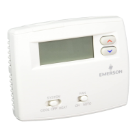
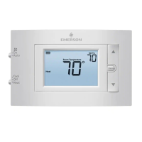
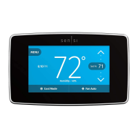
1. Install Sensi thermostat, referring to these terminal
definitions, cross references and wiring diagrams as needed:
OLD
THERMOSTAT
SENSI
THERMOSTAT
CONVENTIONAL
SYSTEM
HEAT PUMP
SYSTEM
RH RH* Power for heating, 24V
RC, R RC* Power for cooling, 24V
C, X, B** C Common wire, 24V
Y, Y1 Y 1st stage cool
1st outdoor
stage heat
Y2 Y2/* 2nd stage cool
2nd outdoor stage
heat and cool
W, W1, W/E,
Aux/E, E
W/E
1st indoor
stage heat
1st stage axillary/
emergency heat
W2*** W2
2nd indoor
stage heat
2nd stage axillary/
emergency heat
G G Indoor blower (fan)
O,B,** O/B O/B
Changeover (reversing valve) connection
for heat pump or zone panel systems
L L no function
“L” terminal
connection
* Two transformer systems (separate RC and RH wires), clip jumper located
on backplate to the right of the terminals.
** Label “B” as “C” only if the old thermostat also had a wire in “O”. If there is no wire
on “O”-label the wire “B”.
*** On Heat Pump system with separate W2 and E wires, label both wires W/E
(2 wires in one terminal).
 Loading...