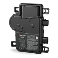
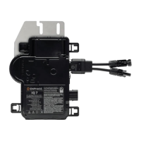
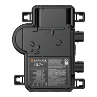
Enphase IQ8P Microinverters
22 © 2024 Enphase Energy Inc. All rights reserved. January 2024
IOM-00002-1.0
Set up and activate monitoring
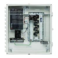
To install the IQ Gateway and set up system monitoring and grid management functions, see the
IQ Gateway Quick Install Guide. This guide leads you through the following:
• Connecting the gateway
• Detecting devices
• Connecting to the Enphase Installer Portal
• Registering the system
• Building the virtual array
NOTE: When the electricity network operator requires a grid profile other than the profile set
on the microinverter, you must select an appropriate grid profile for your installation. You can
set the grid profile through the Enphase Installer Portal, during system registration, or
through the Enphase Installer App at any time. You must have an IQ Gateway to set or
change the grid profile to be compliant with certain jurisdictions.
Troubleshooting
Follow all the safety measures described in this manual. Qualified personnel can use the
following troubleshooting steps if the PV system does not operate correctly.
WARNING: Risk of electric shock. Do not attempt to repair the Enphase
microinverter; it contains no user-serviceable parts. If it fails, contact Enphase
Support to obtain an RMA (return merchandise authorization) number and start
the replacement process.
Status LED indications and error reporting
The following section describes LED indications.
LED operation
Flashing green
Normal operation. AC grid function is normal, and there is communication with
the IQ Gateway.
Flashing orange The AC grid is normal, but there is no communication with the IQ Gateway.
Flashing red The AC grid is either not present or not within the specification.
Solid red
There is an active “DC Resistance Low – Power Off” condition. If the problem
persists, measure resistance between PV+ to EARTH and then PV- to EARTH on
the PV module and then inverter. Anything less than ~7 kΩ will trigger the “DC
Resistance Low – Power Off” condition. Usually, the value is in MΩ on the
inverter or PV module. Swap out faulty PV module or microinverter.
The status LED on each microinverter lights green about six seconds after DC power is applied. It
remains lit solid for two minutes, followed by six green blinks. After that, red blinks indicate that no
grid is present if the system is not yet energized.
Any short red blinks after DC power is first applied to the microinverter indicate a failure during
microinverter start-up.
 Loading...
