L120 Revision A
Disassembly/Reassembly Routing FFCs/cables 40
Confidential
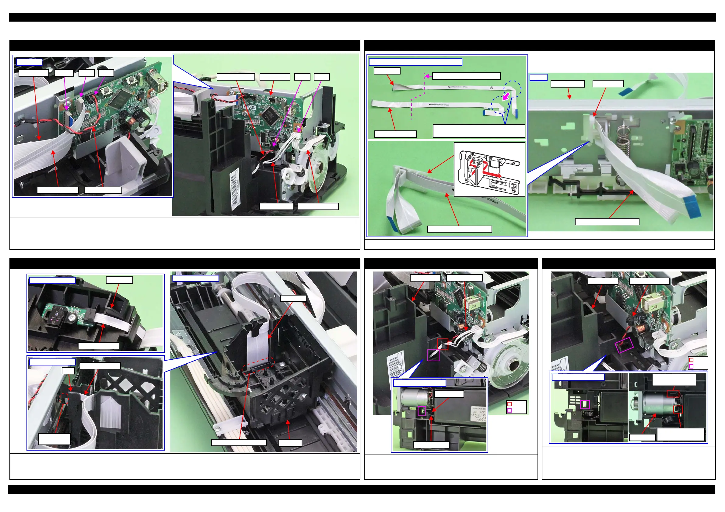
2.4 Routing FFCs/cables
Main Board Assy
Connect the following cables/FFCs to the Main Board as shown in the figure above.
• PF Motor cable (CN13) • PS Unit cable (CN501)
• CR Motor cable (CN12) • CR Encoder FFC (CN6)
• Head FFC (CN102)
CN12CN102Head FFC
CR Encoder FFC
CN6
CR Motor cable
Right side
PF Encoder cablePS Unit cable
PF Motor cable CN13 CN501Main Board
Head FFC (Routing on the Main Frame)
Align the Head FFC and CR Encoder FFC, and then route them through the FFC Holder as shown in the figure above.
Aligning Head FFC with CR Encoder FFC
Head FFC
CR Encoder FFC
Stack the Head FFC over the CR Encoder
FFC to keep the Head FFC on top.
Fold here inside FFC Holder
FFC Holder
Head FFC/CR Encoder FFC
Head FFC (Routing on the CR Unit)
Route the CR Encoder FFC through the rib on the CR Unit and connect it to the connector on the CR Encoder.
Make sure that the CR Encoder FFC is not in contact with the protrusion on the CR Unit.
When routing the Head FFC/CR Encoder FFC, engage the fold to the hook on the CR Unit while aligning their shapes, then connect them to the connector on the Printhead.
Inside of CR Unit
CR Unit
Connector of Printhead
Head FFC
Outside of CR Unit
CR Encoder FFC
Rib
Connector of
CR Encoder
Rearside of CR Unit
CR Encoder FFC
Protrusion
PS Unit
Pull out the PS Unit cable from the hole of the Frame Base first, and then
route it through the rib of the Frame Base.
Put the ferrite core into the position shown in the figure above.
Bottom of Frame Base
PS Unit cable
Ferrite core
PF Motor
Route the PF Motor cable as follows.
1. Pull out the PF Motor cable from the hole of the Frame Base.
2. Install the PF Motor, and secure the PF Motor cable (black) with the rib of
the Frame Base, and then route it through the rib of the Frame Base.
PF Motor
Route PF Motor
cable through rib.
Secure PF Motor
cable (black) with rib.
 Loading...