21
3.0 INSTALLATION
3.1 LOCATION
Several factors should be considered when selecting an in-
stallation site. Adequate ventilation is necessary to provide
cooling, and the amount of dirt and dust to which the machine
is exposed should be minimized. There should be at least 18
inchesofunrestrictedspacebetweenthemachine’ssideand
rear panels and the nearest obstruction to provide freedom
of air movement through the power source.
The installation site should permit easy removal of the ma-
chine’souterenclosureformaintenance.Installingorplacing
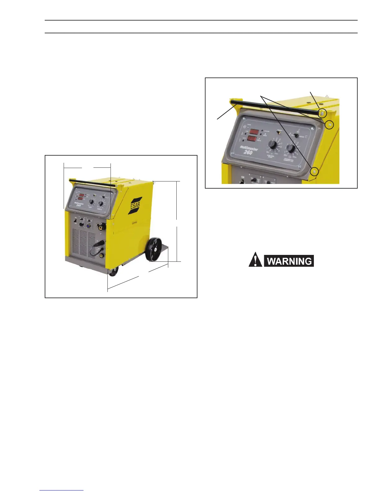
Hex Bolt and Washer
Sheetmetal Screws
Figure 3 - Handle Mount
3.3 ELECTRICAL INPUT CONNECTIONS
Figure 2 - Dimensions
any type of ltering device will restrict the volume of intake
air, thus subjecting the internal components to overheating.
Warranty is void if any type of ltering device is used.
3.2 HANDLE ASSEMBLY INSTALLATION
The Multimaster 260 is factory assembled except for the
front handle which is packed with the machine. The handle
consists of two brackets and a cross bar. To install the handle,
do the following:
A. Remove the two sheetmetal screws on each side of the
power source (see Figure 3).
B. Identify the left and right bracket and mount with the
screws just removed.
C. Place the round bar handle between the two side brackets
and attach with the hex bolts and washers provided with
the handle.
In order to provide a safe and convenient means to completely
remove all electrical power from the machine, it is highly
recommended that a line disconnect switch be installed in
the input circuit of the machine.
Before making electrical input connections to the weld-
ing machine, “Machinery Lockout Procedures” should
be employed. If the connections are to be made from a
line disconnect switch, the switch should be padlocked
in the o position. If the connection is to be made from a
fusebox, remove the fuses and padlock the cover closed.
If no locking facilities are available, attach a red tag to
warn others not to energize the circuit.
3.3.1 INPUT ELECTRICAL REQUIREMENTS
The primary input voltage requirements are shown on the
power source nameplate. The power source is designed
to be operated from 208/230 vac single phase 50/60 Hz or
230/460/575 vac single phase 50/60 Hz.
3.3.2 INPUT PLUG
The input power cord is provided with an attachment plug.
The plug will mate with a 250 volt, 50 Amp receptacle conform-
ing to NEMA 6-50R congura tion (208/230 vac model only).
The receptacle should be wired to a separately fused dis-
connect or circuit breaker by an electrician. This disconnect
or breaker can be wired to a single phase system or two
conductors of a three phase system. A third conductor for
grounding must be connected between the disconnect and
the receptacle.
20”
32”
42”
Bar
SECTION 3 INSTALLATION
 Loading...