27
4.2 OPTIONAL CONTROLS
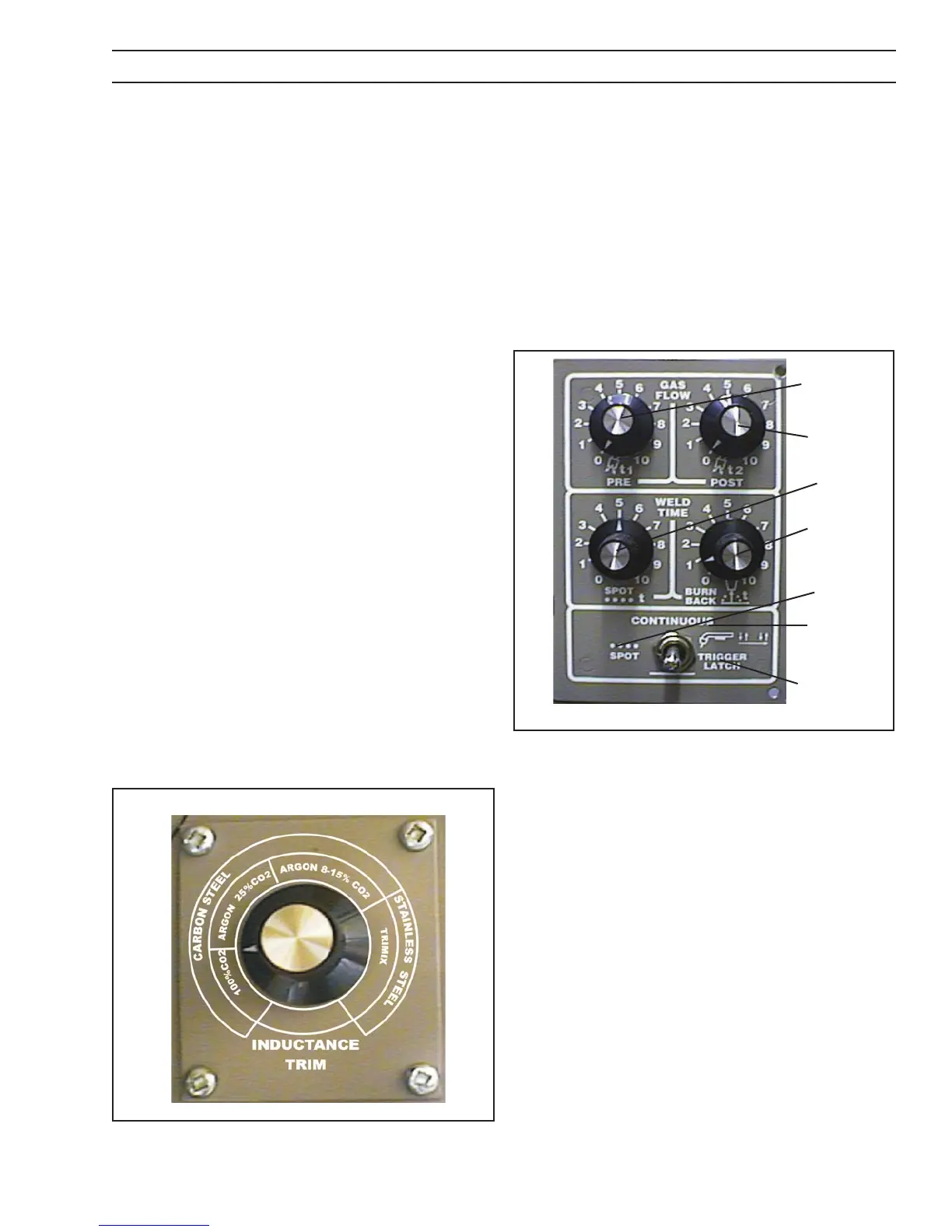
4.2.1 INDUCTANCE TRIM (OPTIONAL)
PN-0558001794 (Figure 14)
Inductance is used to optimize short circuiting arc perfor-
mance by changing the current rise and fall time of each
short circuit. This results in improved spatter control, weld
bead wetting and arc stability. It is HIGHLY RECOMMENDED
that the Inductance Trim option be used for optimum short
arc welding performance with stainless steel wires.
The INDUCTANCE TRIM is installed inside the wire spool
compartment, above the wire feed motor, to the left of the
Burnback adjustment. The “easy to set” dial is calibrated by wire
alloy (Carbon Steel and Stainless Steel) and Shielding gas:
100% CO
2
Argon - 25% CO
2
Argon - 8 to 15% CO
2
Trimix (Stainless Helium Mixtures)
The short circuiting Mig arc performance will change from
a high short circuit frequency, fast reacting arc, to a lower
short circuit frequency, soft and less spattering arc as the
dial is turned clockwise. The optimized arc performances
will vary depending on shielding gas, wire diameter and
alloy. Gases and alloys other than those indicated can also
be optimized with this control. The operator can adjust this
control as desired to optimize personal preferences of weld-
ing characteristics.
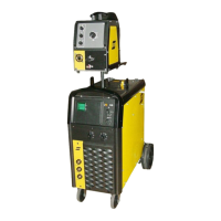
4.2.2 PREFLOW/POSTFLOW/SPOT/BURNBACK
OPTIONAL PN0558001795 FIGURE 15
This optional control is mounted in place of the standard
burnback control inside the wire spool compartment. A
description of the module follows:
A. Preow/Postow - The PREFLOW control sets the time
of the preow shielding gas before the wire starts feed-
ing (0-1.5 sec.). The POSTFLOW control sets the time
the shielding gas remains “ON” after the arc is turned
“OFF” (0-7.5 sec.).
Figure 14 - Inductance Trim
Figure 15 - Preow/Postow/Spot/Burnback
B. Spot Weld Time - This dial sets the spot weld time from 0
to 5 seconds and is controlled by a current detect switch.
The timer does not start until current is detected to insure
consistent results.
C. Burnback Timer - See 4.1.11
D. Spot Weld Switch Position - With the toggle switch in
the SPOT (left) position, the SPOT timer is turned “ON”,
and the spot weld time is controlled by the SPOT WELD
TIMER dial.
E. Continuous Position - With the toggle switch in the
CONTINUOUS (center) position, the welding continues
as long as the Mig gun trigger is depressed.
F. Trigger Lock Position - With the toggle switch in the TRIG-
GER LOCK (right) position, the welding process begins
when the gun trigger is depressed. Once the welding
process has started, the gun trigger may be released with-
out aecting the welding process. To stop the welding
operation, the gun trigger must be depressed a second
time. This allows a continuous weld without having to
continuously depress the gun trigger.
Continuous
“ON”
Trigger Latch
“ON”
Spot “ON”
Spot Time
Preow
Time
Postow Time
Burnback
Time
SECTION 4 OPERATION
 Loading...