24
3.7.4 SPOOL BRAKE DRAG ADJUSTMENT
Spool brake disc friction should provide enough drag to keep
the wire spool from spinning freely after wire feed stops. If
adjustment is required, turn the adjusting screw inside the
spindle housing clockwise to increase drag or counterclock-
wise to decrease it. Drag should be just enough to limit
wire overrun.
3.8 CONNECTION OF SHIELDING GAS SUPPLY
3.8.1 R33FM580 REGULATOR
The R-33-FM-580 regulator is an adjustable regulator designed
for use with Argon, Helium, and C-25 (75% Argon/25% CO
2
)
gas service. Table 2 table provides the recommended ow
ranges for the R-33-FM-580 regulator.
Argon 10-50 cfh
Helium 150-230 cfh
C-25 10-50 cfh
Table 2 - Typical Flow Rates
A. With the cylinder cap in place, CAREFULLY slide the
cylinder of gas onto the Multimaster 260 cylinder rack.
B. Secure the cylinder to the unit using the chain provid-
ed.
C. Unscrew the cylinder cap.
Do not clamp regulator cap in a vise or grip it with a pair
of pliers. Distortion of cap can jam the internal parts and
cause excessively high delivery pressure as well as weaken
the threaded joint to the regulator body. This may cause
the cap to y o and possibly injure personnel in area.
D. Open the cylinder valve slightly, for an instant, to blow
out any dust or dirt that may have collected in the valve
outlet. BE SURE to keep your face away from the valve
outlet to protect your eyes.
E. Attach the regulator to the cylinder valve. Align the
regulator so that the owmeter is vertical and then
tighten the connection nut with a 1-1/8 in. open end
or adjustable wrench. To prevent damaging the O-ring
seals and plastic tube, do not use the owmeter tube as
a‘handle’whenattachingtheregulator.
F. Close the ow control valve on the owmeter.
G. Attach the gas hose from the rear of the Multimaster 260
to the regulator outlet connection.
Never stand directly in front of or behind the regulator
when opening the cylinder valve. Always stand to one
side.
H. Open the cylinder valve SLOWLY a fraction of a turn. This
will prevent damage to the gauge and critical components
in the regulator. When the gauge needle stops moving,
then open the cylinder valve fully.
I. Using a leak test solution, such as P/N 998771 (8 oz. ctr)
or soapy water, test for leakage around the cylinder
valve stem, the regulator inlet connection, and the hose
connections at the regulator. Correct any leaks before
starting work.
3.8.1 TO REGULATE FLOW
Flow is controlled by adjusting the owmeter valve until de-
sired ow is indicated by the ball oat in the owmeter tube.
Always take the reading across the TOP of the ball.
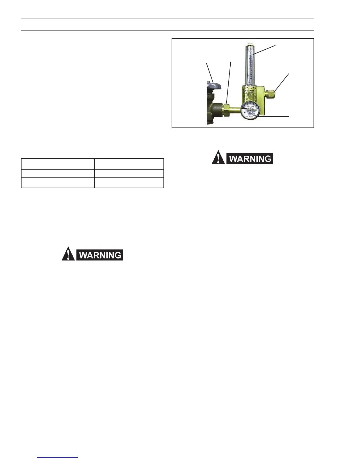
Figure 10 - R-33 Regulator
Cylinder Valve
Connection
Nut
Flow Tube
Control Valve
Pressure
Gauge
SECTION 3 INSTALLATION
 Loading...