EVCO S.p.A. c-pro 3 nano | Hardware Manual ver. 1.0 | Code 114CP3NE104
page 7 of 26
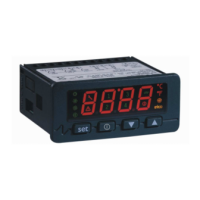
2 DESCRIPTION
The picture below shows the appearance of the devices.
The table below describes each part of the devices.
PART DESCRIPTION
1 user interface
2
Micro-switch for:
- fitting the termination resistor for the RS-485 MODBUS port
- fitting the termination resistor for the CAN port
3 Micro USB connector for USB port
4 plug-in screw terminal block for digital outputs 1... 6
5 plug-in screw terminal block for digital output 7
6
Micro-Fit connector for:
- device power supply
- auxiliary power supply (12 VDC)
- analogue inputs 1... 7
- digital inputs 1... 3
- analogue outputs 1... 2
- INTRABUS port
7 Micro-Fit connector for CAN port
8
Micro-Fit connector for:
- auxiliary power supply (5 VDC)
- analogue inputs 8... 9
- digital inputs 4... 5
- analogue outputs 3... 4
- RS-485 MODBUS port
- CAN port
For more information see subsequent sections.
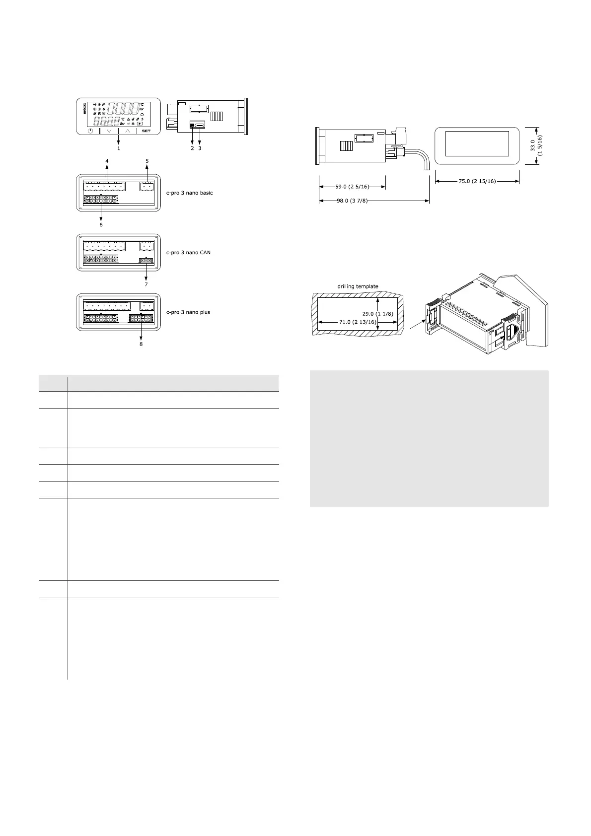
3 MEASUREMENTS AND INSTALLATION
3.1 Measurements
The picture below shows the measurements of the devices.
Measurements are expressed in mm (inches).
3.2 Installation
The picture below shows the installation of the devices.
To be fitted to a panel, snap-in brackets provided.
INSTALLATION PRECAUTIONS
- The thickness of the panel must be between 0.8 and 2.0 mm (1/32 and
1/16 in).
- Ensure that the working conditions are within the limits stated in the
TECHNICAL SPECIFICATIONS section.
- Do not install the device close to heat sources, equipment with a strong
magnetic field, in places subject to direct sunlight, rain, damp, excessive
dust, mechanical vibrations or shocks.
- In compliance with safety regulations, the device must be installed
properly to ensure adequate protection from contact with electrical parts.
All protective parts must be fixed in such a way as to need the aid of a tool
to remove them.

 Loading...