EVCO S.p.A. c-pro 3 nano | Hardware Manual ver. 1.0 | Code 114CP3NE104
page 9 of 26
dry contact digital input)
11 digital input 5 (dry contact)
12
analogue input 9 (for NTC probes, 0-5 V ratiometric transducers, 0-
10 V, 0-20 mA or 4-20 mA transducers; can be configured also for
dry contact digital input)
Connector 3
No. DESCRIPTION
1 K1, K2 and K3 digital output common contact
2 K1 digital output normally open contact (3 A res. @ 250 VAC)
3 K2 digital output normally open contact (3 A res. @ 250 VAC)
4 K3 digital output normally open contact (3 A res. @ 250 VAC)
5 K4, K5 and K6 digital output common contact
6 K4 digital output normally open contact (3 A res. @ 250 VAC)
7 K5 digital output normally open contact (3 A res. @ 250 VAC)
8 K6 digital output normally open contact (3 A res. @ 250 VAC)
Connector 4
No. DESCRIPTION
1 K7 digital output common contact
2 K7 digital output normally open contact (3 A res. @ 250 VAC)
Connector 5
USB port.
Connector 6
No. DESCRIPTION
1 reference (GND)
2 signal - CAN port
3 signal + CAN port
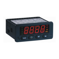
4.2 Connection to the power supply
The picture below shows the c-pro 3 nano plus connection to the power supply.
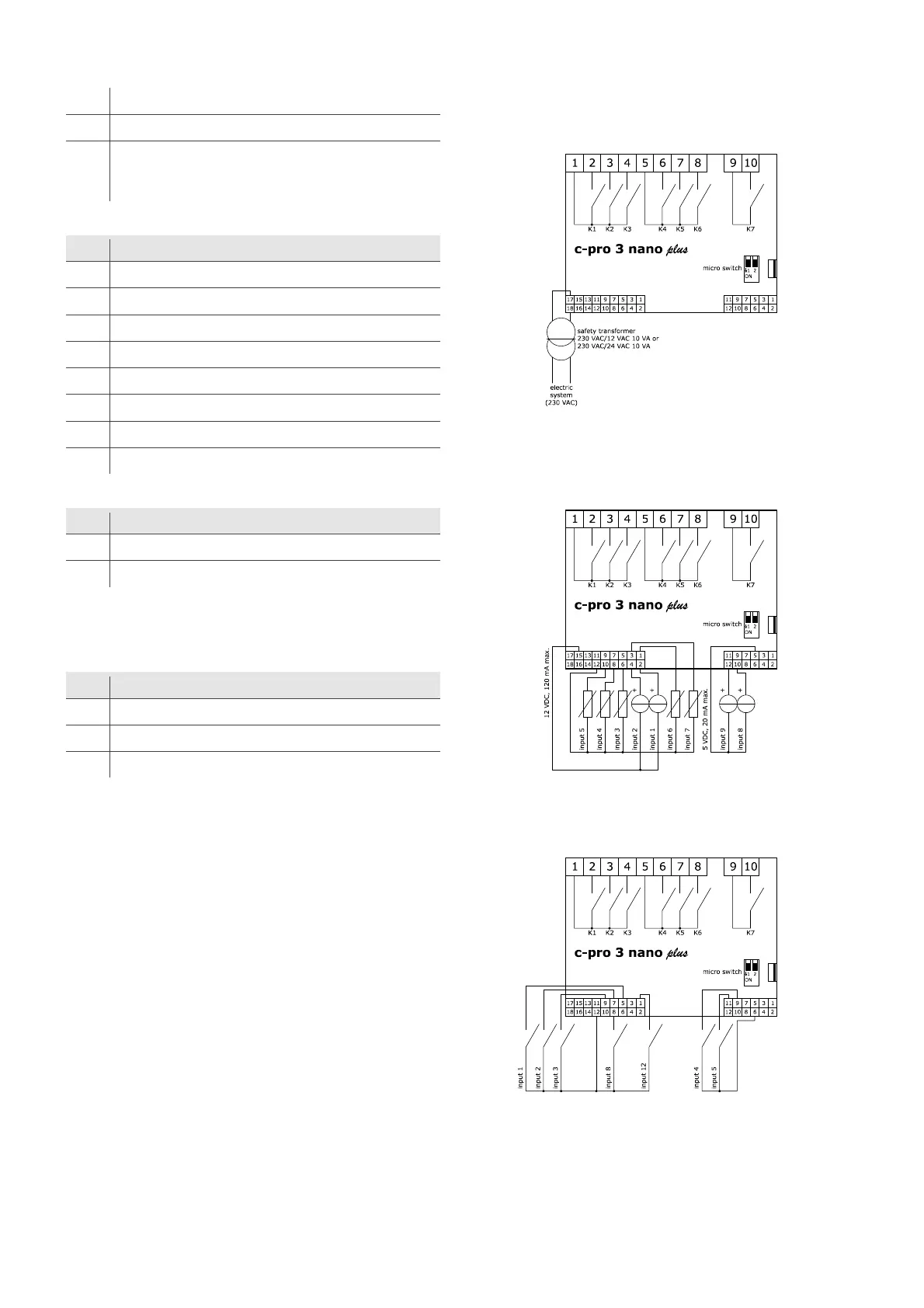
4.3 Analogue input wiring diagram
The picture below shows an example of c-pro 3 nano plus analogue input
connection.
4.4 Digital input wiring diagram
The picture below shows the c-pro 3 nano plus digital input connection.

 Loading...