EVCO S.p.A. c-pro 3 nano | Hardware Manual ver. 1.0 | Code 114CP3NE104
page 8 of 26
4 ELECTRICAL CONNECTION
N.B.
- Do not supply further devices with the same transformer.
- Use cables of an adequate section for the current running
through them.
- To reduce any electromagnetic interference connect the power
cables as far away as possible from the signal cables and, if
necessary, connect to a RS-485 MODBUS network and/or a CAN
network by using a twisted pair.
- The device is not compatible with controllers, I/O expansions and
remote user interfaces of the c-pro series.
- For more information see section TECHNICAL SPECIFICATIONS.
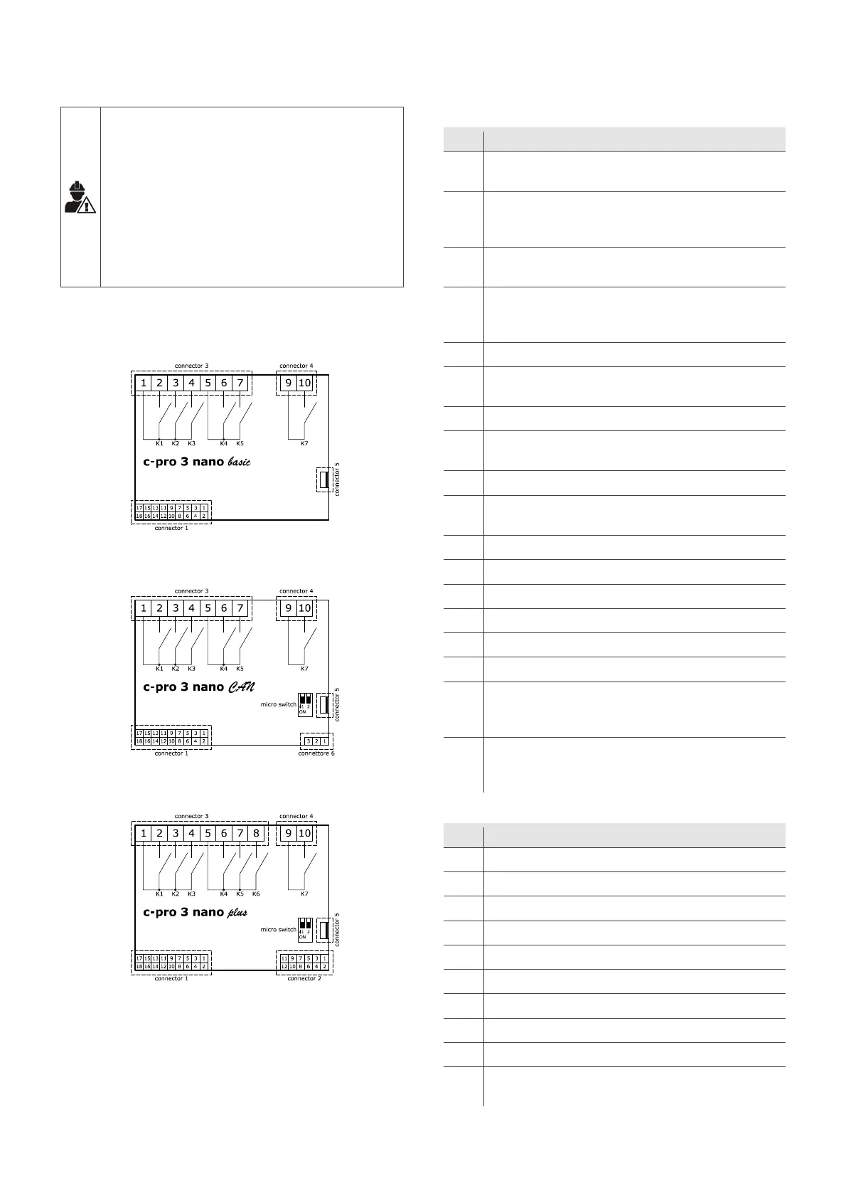
4.1 Connectors
The picture below shows the c-pro 3 nano basic connectors.
The picture below shows the c-pro 3 nano CAN connectors.
The picture below shows the c-pro 3 nano plus connectors.
The tables below describe the connectors.
Connector 1
No. DESCRIPTION
1
analogue input 6 (for PTC, NTC or Pt 1000 probes; can be
configured also for dry contact digital input)
2
analogue input 1 (for NTC probes, 0-5 V, 0-10 V, 0-20 mA or 4-20
mA transducers; can be configured also for dry contact digital
input)
3
analogue input 7 (for PTC, NTC or Pt 1000 probes; can be
configured also for dry contact digital input)
4
analogue input 2 (for NTC probes, 0-5 V, 0-10 V, 0-20 mA or 4-20
mA transducers; can be configured also for dry contact digital
input)
5 digital input 1 (dry contact and for pulse trains up to 2 KHz)
6
analogue input 3 (for PTC, NTC or Pt 1000 probes; can be
configured also for dry contact digital input)
7 digital input 2 (dry contact and for pulse trains up to 2 KHz)
8
analogue input 4 (for PTC, NTC or Pt 1000 probes; can be
configured also for dry contact digital input)
9 digital input 3 (dry contact)
10
analogue input 5 (for PTC, NTC or Pt 1000 probes; can be
configured also for dry contact digital input)
11 analogue output 1 (for 0-10 V, PWM or phase cutting signal)
12 reference (GND)
13 analogue output 2 (for 0-10 V, PWM or phase cutting signal)
14 INTRABUS port data
15 auxiliary power supply (12 VDC)
16 reference (GND)
17
device power supply (12 VAC or 24 VAC/DC, according to the
model). If the device is fed by DC power, it is not necessary to take
account of the supply voltage polarity
18
device power supply (12 VAC or 24 VAC/DC, according to the
model). If the device is fed by DC power, it is not necessary to take
account of the supply voltage polarity
Connector 2
No. DESCRIPTION
1 signal + RS-485 MODBUS master/slave port
2 signal + CAN port
3 signal - RS-485 MODBUS master/slave port
4 signal - CAN port
5 ratiometric transducer power supply 0-5 V (5 VDC)
6 reference (GND)
7 analogue output 3 (for 0-10 V, 0-20 mA or 4-20 mA signal)
8 analogue output 4 (for 0-10 V, 0-20 mA or 4-20 mA signal)
9 digital input 4 (dry contact)
10
analogue input 8 (for NTC probes, 0-5 V ratiometric transducers, 0-
10 V, 0-20 mA or 4-20 mA transducers; can be configured also for

 Loading...