12
Maintenance (continued)
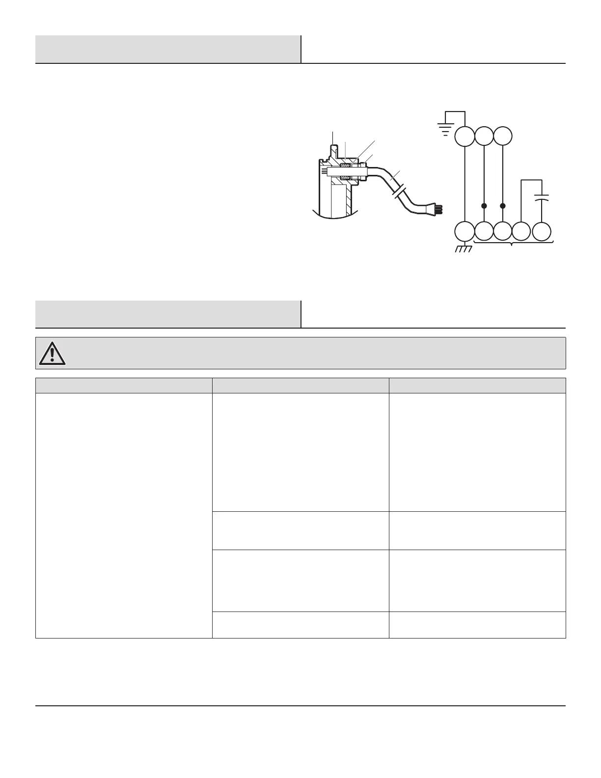
POWER CABLE CONNECTION
1. Place the gland nut (17), friction ring (16), and grommet (15)
onto the cord and slide the cord through the housing end (19).
2. Place the O-ring (23) into the groove on the housing end piece
(19) and slide the end piece onto the motor housing (25) being
careful not to damage the O-ring.
3. Place the pump support (22) onto the lower studs (26) and
place the lock washers (21) and hex nuts (20) onto the studs
and tighten.
4. Insert the grommet (15) and friction ring (16) into the housing
end piece (19).
5. Apply pipe sealant to the gland nut (17), screw into the end
piece, and torque the gland nut (17) to 17.5 ft. lbs to prevent
water leakage.
Motor Leads
Capacitor
Power Leads
Green
Black
White
GL1L2
GT1T2
19
15 16
17
18
Troubleshooting
WARNING: Ensure the pump is disconnected from the power source before attempting to service or remove any component.
Problem Solution Probable Cause
The pump will not turn. □ The electrical connection is poor, the
fuse is blown, there is a tripped breaker,
or other interruption of power.
□ The power supply is incorrect.
□ Check all electrical connections for
security.
□ Have an electrician measure the cur-
rent in the motor leads. If the current is
within ±20% of locked rotor Amps, the
impeller is probably locked.
□ If the current is 0, overload may be
tripped. Remove the power, allow the
pump to cool, then recheck the current.
The oat movement is restricted. Reposition the pump or clean the basin as
required to provide adequate clearance for
oat.
The motor is defective. □ Check the winding insulation
(Megger Test) and winding resistance.
If the check is outside of range, dry and
recheck. If still defective, replace per the
service instructions.
The liquid level is insufcient. □ Make sure the liquid level is at least
equal to the suggested turn-on point.
 Loading...