Installation
8.
310
· 308 ·
Ref.1912
DDS
HARDWARE
The pinout of the MSP connector is described in the following table:
RS-232/422 serial line connection with a DRIVE
The RS-232/422 connection of the drive (only MMC or CMC models) is
made through the X6 connector on the front panel of the module. See figure.
This port is accessed through a 9-pin male SUB-D type connector and can
establish communication with other devices using the RS-232/422 protocol.
The pinout of connector X6 (RS-232/422 serial line) is described in table
T.
H8/7.
T. H8/6 Pinout of the MSP connector. * C.L. means <Current Loop>.
Pin Signal Pin Signal
1
Not Connected
14
IKT OUT
2
TxRS232 OUT
15
IKR OUT
3
RxRS232 IN
16
+5 V DC (reserved)
4
RTS RS232 OUT
17
Not Connected
5
CTS RS232 IN
18
* R x C.L. +IN
6
Not Connected
19
Not Connected
7
GND
20
Not Connected
8
Not connected
21
Not Connected
9
* TxC.L. + OUT
22
TxRx485+IN/OUT
10
TxRx485-IN/OUT
23
TxRS422 +OUT
11
* TxC.L. - OUT
24
RxRS422 -IN
12
TxRS422 - OUT
25
* R x C.L. - IN
13
RxRS422 +IN
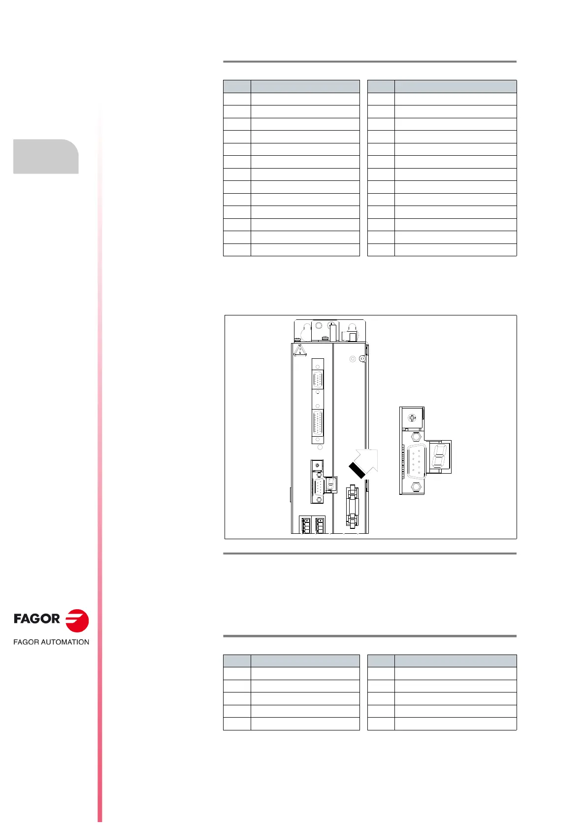
F. H8/48
Connector X6 of the drive (MMC or CMC) for the RS-232/422 connection.
T. H8/7 Pinout of connector X6 (RS-232/422).
Pin Signal Pin Signal
1
Not Connected
6
TxD 422
2
RxD 232
7
#TxD 422
3
TxD 232
8
RxD 422
4
+5 V ISO
9
#RxD 422
5
GND ISO
X4
X3
X1
STATUS
DISPLAY
X5
X6
SL2
SL1
POSITIONING DRIVE
1
5
6
9
NODE
SELECT
 Loading...