Power supplies
2.
94
Ref.1912
DDS
HARDWARE
· 80 ·
Other elements
Besides the various connectors, the front panel of these power supplies has
other elements that are mentioned next.
Status display
The 7-segment status display shows the system start-up sequence as well
as the possible errors and warnings that could come up. For further detail,
see the section «turning the module on» at the end of this chapter and go to
chapter
14. ERROR CODES AND MESSAGES at the RPS power supplies in the
«man_dds_soft.pdf» manual to interpret the errors and/or warnings
displayed.
Selector switches. DC BUS command voltage
The two switches located between the electronic status display and the
RESET button may be used to program a particular value of the voltage
command at the power DC BUS DC.
Thus, depending on the selected switch settings (configurations), the power
supply will work in booster mode (RPS mode)
, boosting the line voltage
rectified at the DC BUS or in rectifier mode (RB6 mode) keeping the line
voltage rectified at the DC BUS regardless of the value of the line voltage.
The user must configure the RPS power supply with:
1. The minimum bus voltage required to properly meet the features required
by the system (especially with the needs of the motors installed) and
2. A voltage command no lower than 1.48xVline, approximately.
The possible configuration it offers are:
RPS power supplies will always work in the mode configured by the
switches: either RPS mode or RB6 mode.
1. RPS operating mode. Boost the voltage value set in VP5. The approx.
value of the bus voltage will be the one set by the user in parameter VP5 of
the RPS power supply. By default, this value is 650 V DC. MAX. 725 V DC.
Select this configuration if 440 V AC V line 420 V AC.
If it cannot properly meet the features required by the system, change the
value of VP5.
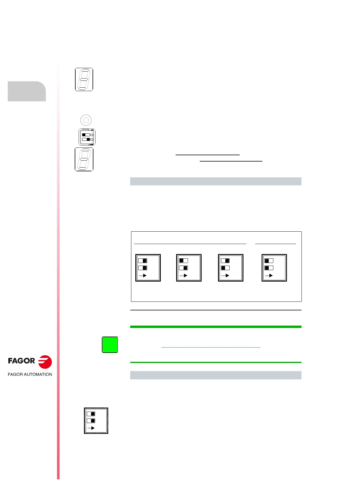
Configurations
F. H2/39
DC BUS voltage command selector switches. Configurations.
ON
ON
ON
ON
VP5 VDC 625 VDC 600 VDC
1.41xVmains
RPS MODE RB6 MODE
S1
S2
S1
S2
S1
S2
S1
S2
·1· ·2· ·3· ·4·
It represents the moving element of each switch.
INFORMATION.The power supplies are factory set according to option 2,
i.e. 625 V DC.
IMPORTANT. Option 4, configuration in RB6 MODE, it only works
when having RPS power supply version 03.01 or higher. When having an
older version, bear in mind that the DC bus voltage command set at 675 V
DC.
Meaning
 Loading...