Power supplies
2.
Ref.1912
· 75 ·
DDS
HARDWARE
Connector description
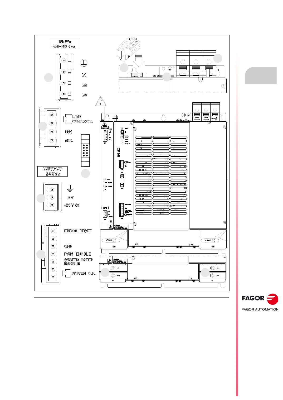
The following figure shows the regenerative regulated power supply RPS-80 and its connector layout:
F. H2/35
Regenerative regulated power supply, RPS-80. Connectors.
1. Power connector for the three-phase mains.
2. Line voltage input connector for synchronism.
3. Ground connection for the mains cable.
4. Power DC BUS supplying power to the modular drives through metal bars.
X1. Connector of the integrated auxiliary three-phase power supply with line voltage.
X2. Output connector of the auxiliary 24 V DC power supply integrated into the module.
X3. Connector to be used to open/close the main internal contactor (NS1-NS2 pins) and acknowledge
externally the status of the contactor (LINE CONTACT pins).
X4. Connector to communicate with the modular drives through the internal bus.
X6. Connector for the basic control signals.
top
view
4
4
X6
X2
X4
X3
3
1
2
X1
CAUTION.
AC touch current greater than 3.5 mA.
Install ground wire of at least 10 mm² (Cu) or 16
mm² (Al).
L1 L2 L3
 Loading...