9.
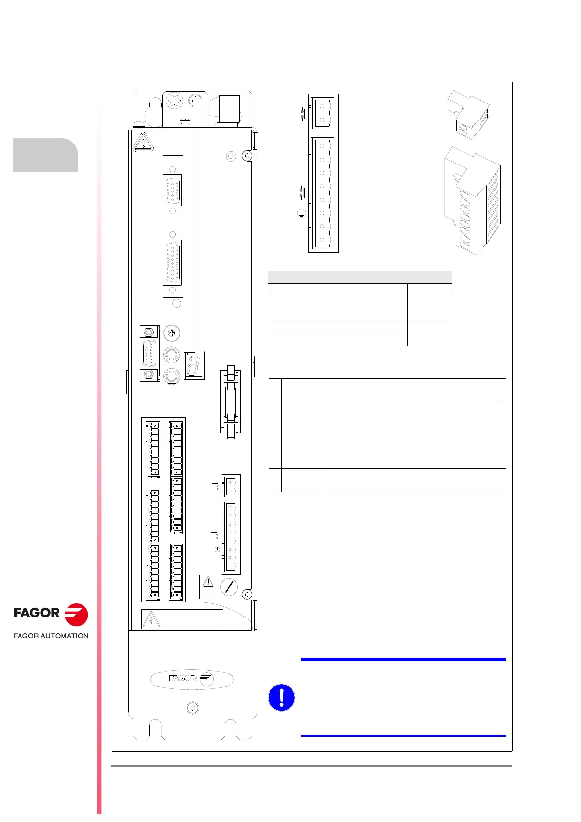
Aerial male connectors X2 and X7. Mechanical data.
Female connector X2. Electrical data.
8-pin connector whose 3 pins to consider are:
See sub-section: X2 connector in chapter 3 of this manual.
Female connector X7. Electrical data.
2-pin (AS1-AS2) connector associated with the (N.C.,
Normally Closed) contact of an internal safety relay with
guided pins of free potential. The state of the Drive Enable
input is open high “H”.
Dielectric strength: 1800 Vrms
Contact data
:
Current Imax = 1 A
Voltage = 24 V DC
See sub-section: X7 connector in chapter 3 of this manual.
Drive Enable electrical protections
Connector data
Nr of poles (X2/X7) 8/2
Gap (mm) 5
Min./max. tightening torque (N·m) 0.5/0.6
Screw thread M3
Min./max. section (mm²) 0.2/2.5
1 GND
0 V DC reference for
Drive Enable and Speed Enable
2
DRIVE
ENABLE
24 V DC.
Drive current enable
0 V DC.
STO (
Safe Torque Off, integrated channel
input)
24 V DC ±10 %, I< 50 mA.
3
SPEED
ENABLE
24 V DC. Drive speed enable.
Out of certification.
MANDATORY.
Install a 1 A slow fuse - F of 1 A to limit the current
at the Drive Enable input.
See fuse
- F in figures F. H9/2 and F. H9/3.
Use a SELV/PELV power supply for the Drive
Enable and AS1-AS2 circuits.
SAFE TORQUE OFF
Drive Enable input
 Loading...