www.fastech-motions.com - 12
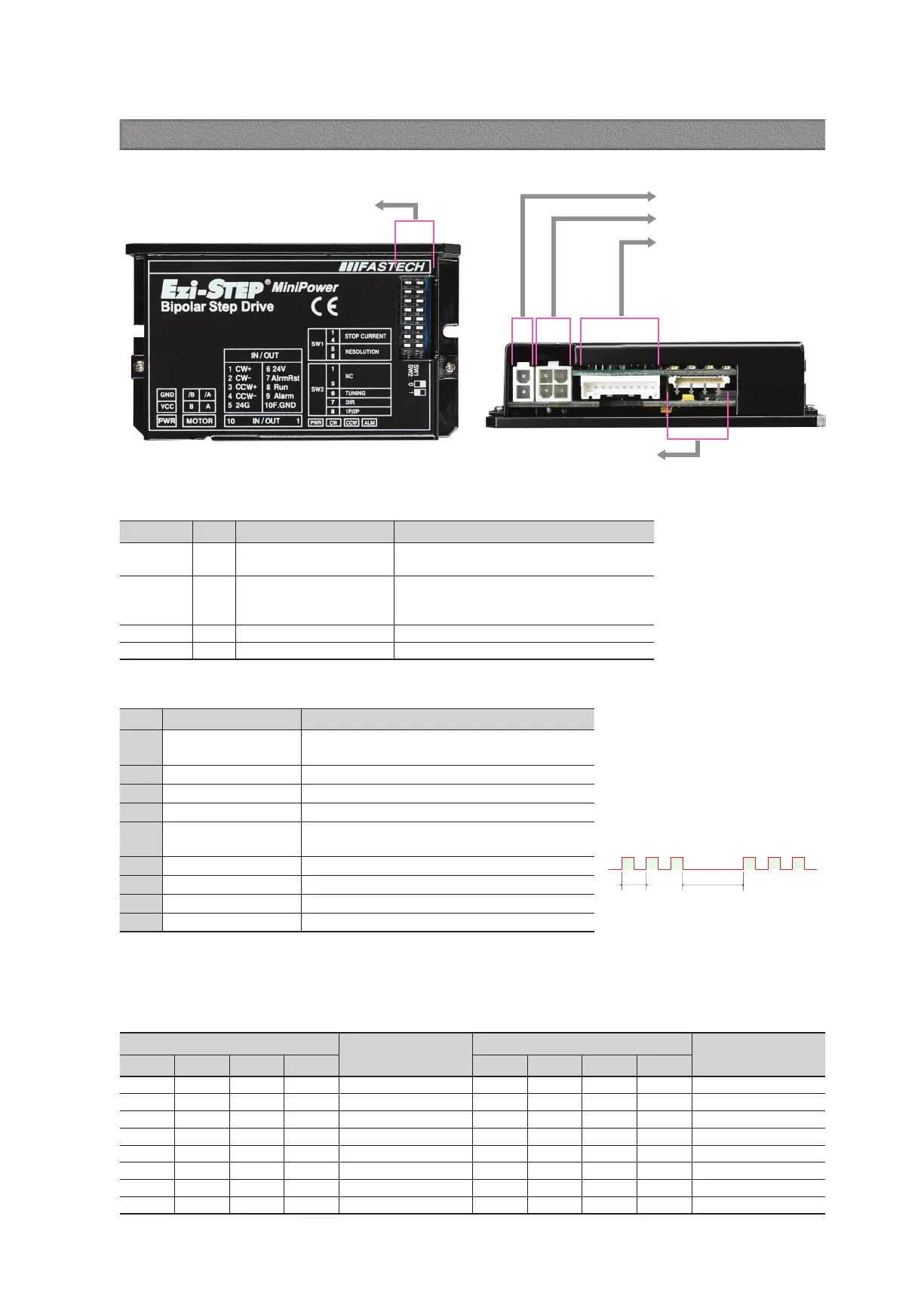
Power connection(CN1)
Motor connection(CN2)
Drive status LED
Input/Output singnal
connection(CN3)
Setup DIP switch(SW1, SW2)
Switch Position
STOP Current (%)
Switch Position
STOP Current (%)
4 3 2 1 4 3 2 1
ON ON ON ON 10 OFF ON ON ON 90
ON ON ON OFF 20 OFF ON ON OFF 100
ON ON OFF ON 30 OFF ON OFF ON 10
ON ON OFF OFF 40 OFF ON OFF OFF 10
ON OFF ON ON 50
*1
OFF OFF ON ON 10
ON OFF ON OFF 60 OFF OFF ON OFF 10
ON OFF OFF ON 70 OFF OFF OFF ON 10
ON OFF OFF OFF 80 OFF OFF OFF OFF 10
12.2 Stop Current Setting Switch(SW1.1~SW1.4)
Stop Current means the motor current value automatically set in 0.1 sec after motor stops. This is to prevent the overheart of a motor when
the motor is under long time idling. The un itof the selection value is a percentage.
*1 : Default : 50%
12.1 Drive Status LED
◆ Protection functions and LED flash times
Indication Color Function ON/OFF Condition
PWR Green Power input indication
Lights when power is ON Flashs when motor is
Free status
ALM Red Alarm indication
Flash when protection function is activated
(Identifiable which protection mode is activated
by counting the blinking times)
CW Yellow Motor Rotation Direction Lights when motor rotate CW direction
CCW Orange Motor Rotation Direction Lights when motor rotate CCW direction
Times Protection Conditions
1 Over Current Error
The current through power devices in drive exceeds
the limit value
*1
2 Over Speed Error Motor speed exceeded 3,000 [rpm]
3 Step Out Error Abnormally motor do not followed pulsed input
5 Over Temperature Error Internal temperature of a motor drive exceeded 85℃
6
Over Regenerative
Voltage Error
Back EMF more than 70V
7 Motor Connect Error Power is ON without connection of motor cable to drive
9 Motor Voltage Error Motor voltage is below 36V
11 System Error Error occurs in drive system
12 ROM Error Error occurs in Parameter storage Device(ROM)
*1 : Limit value depends on motor model
Alarm LED flash
(Ex, Step Out Error)
2.0s0.5s
12. Settings and Operation [Ezi-STEP-MPB series]
 Loading...