www.fastech-motions.com - 13
1
10
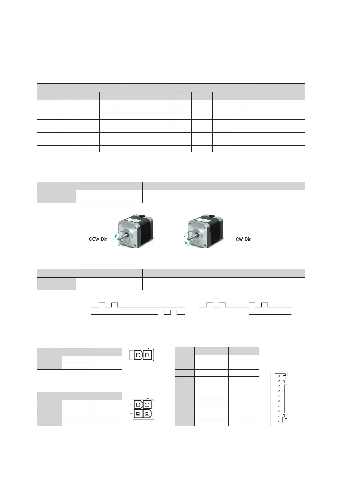
12.7 Motor Connector(CN2)
NO. Function I/O
1 A Phase Output
2 B Phase Output
3 /A Phase Output
4 /B Phase Output
12.6 Power Connector(CN1)
NO. Function I/O
1 24VDC Input
2 GND Input
12.8 Signal Connector(CN3)
NO. Function I/O
1 CW+(Pulse+) Input
2 CW-(Pulse-) Input
3 CCW+(Dir+) Input
4 CCW-(Dir-) Input
5 EXT_GND Input
6 EXT_24VDC Input
7 Alarm Reset Input
8 Run/Stop Output
9 Alarm Output
10 F.GND ----
2
1
4
3
12
12.5 Pulse Input Setting Switch(SW2.8)
Indication Switch Name Functions
1P/2P
Pulse input mode
Select Switch
Selectable 1-Pulse input mode or 2-Pulse input mode as Pulse input signal.
ON: 1-Pulse mode OFF: 2-Pulse mode ※ Default: 2-Pulse mode
CW(Pulse) Pin
CCW(Dir) Pin
Rotational Direction CW CWCCW CCW
2-Pulse Mode 1-Pulse Mode
Direction setting
switch: ON
Direction setting
switch: OFF
12.4 Rotational Direction Setting Switch(SW2.7)
Indication Switch Name Functions
DIR
Rotational Direction
Select Switch
Based on CW(+Dir signal) input to driver.
ON: CCW(-Direction) OFF: CW(+Direction) ※ Default: CW mode
Switch Position
Pulse/
Revolution
Switch Position
Pulse/
Revolution
8 7 6 5 8 7 6 5
ON ON ON ON 500 OFF ON ON ON 6,400
ON ON ON OFF 1,000 OFF ON ON OFF 8,000
ON ON OFF ON 1,600 OFF ON OFF ON 10,000
*1
ON ON OFF OFF 2,000 OFF ON OFF OFF 20,000
ON OFF ON ON 3,200 OFF OFF ON ON 25,000
ON OFF ON OFF 3,600 OFF OFF ON OFF 36,000
ON OFF OFF ON 4,000 OFF OFF OFF ON 40,000
ON OFF OFF OFF 5,000 OFF OFF OFF OFF 50,000
12.3 Resolution Setting Switch(SW1.5~1.8)
*1 : Default : 10,000
The Number of pulse per revolution.
 Loading...