www.fastech-motions.com - 22
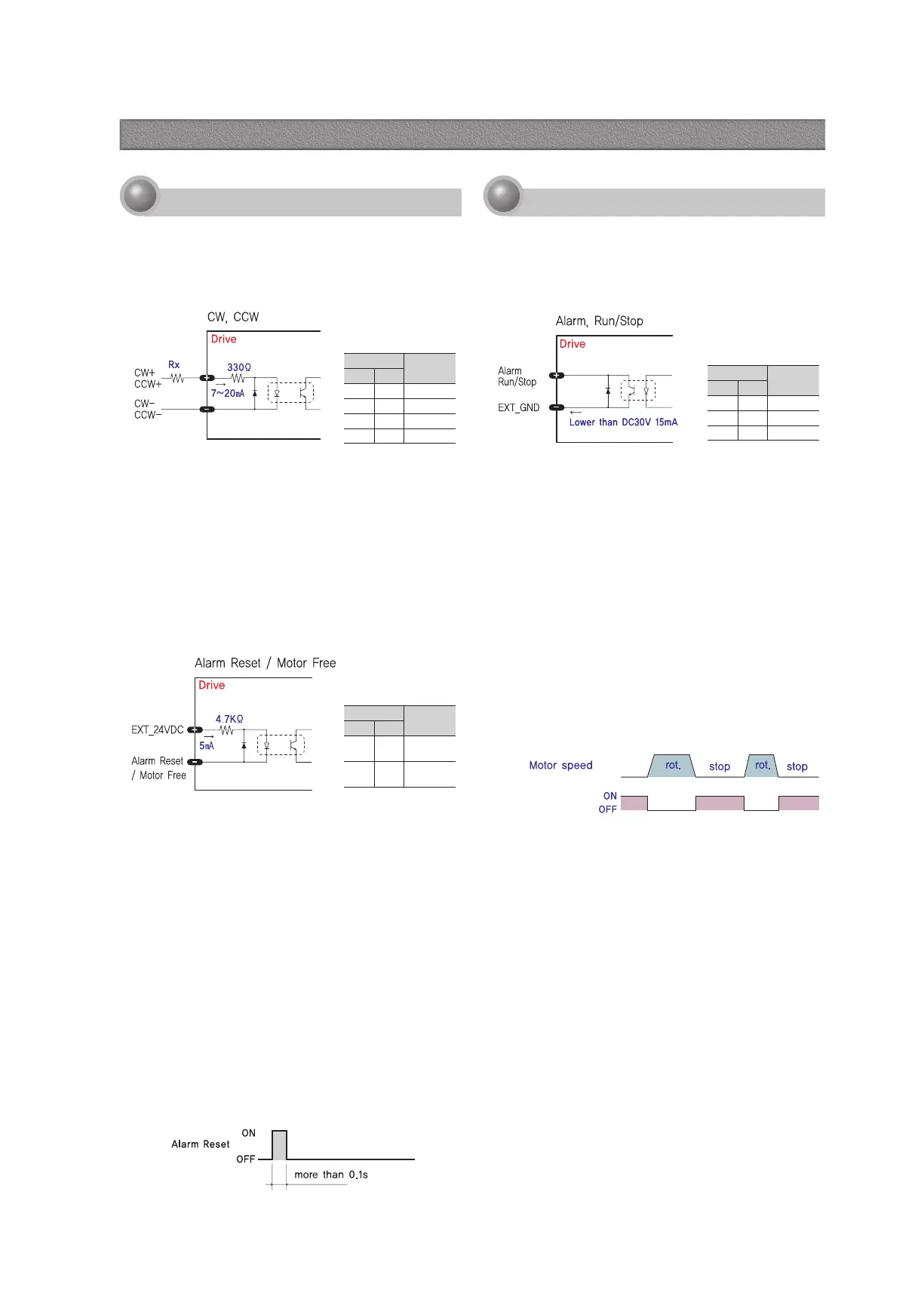
◆ CW, CCW Input
This signal can be used to receive a positioning pulse
command from a user host motion controller. The user can
select 1-pulse input mode or 2-pulse input mode. The input
schematic of CW, CCW is designed for 5V TTL level. When
using 5V level as an input signal, the resistor Rx is not used
and connect to the driver directly. When the level of input
signal is more than 5V, Rx resistor is required. If the resistor
is absent, the drive will be damaged. If the input signal level
is 12V, Rx value is 680ohm and 24V, Rx value is 1.8Kohm.
◆ Motor Free Input
This input can be used only to adjust the position by manually
moving the motor shaft from the load-side. By setting the
signal [ON], the drive cuts off the power supply to the motor.
Then, one can manually adjust output position. When setting
the signal back to [OFF], the drive resumes the power supply
to the motor and recovers the holding torque. When driving a
motor, one needs to set the signal [OFF]. In normal operations
set the signal [OFF] or disconnect a wire to the signal. It
operates reversely compare to Normal mode, when you set
Inverse mode.
Alarm Reset signal line is also used for Motor Free signal.
◆ Alarm Reset Input
When a protection mode has been activated, a signal to this
Alarm Reset input cancels the Alarm output. By setting the
alarm reset input signal [ON], cancel Alarm output. Before
cancel the Alarm output, have to remove the source of alarm.
[Caution] If Alarm Reset input signal still remains [ON], motor will be
Free state. Keep in mind to change [ON]→[OFF] state.
1
Input Signal
Input signals of the drive are all photocoupler protected.
The signal shows the status of internal photocouplers
[ON: conduction], [OFF: Non-conduction], not displaying
the voltage levels of the signal.
◆ Alarm Output
The Alarm output indicates [OFF] when the drive is in a
normal operation. If a protection mode has been activated, it
goes [ON]. A host controller meeds to detect this signal and
stop sending a motor driving command.
When the drive detects an abnormal operation such as
overload of overcurrent of a motor, it sets the Alarm output to
[ON], flash the Alarm LED, disconnects the power to a motor
and stops the motor, simultaneously.
It operates reversely compare to Normal mode, when you set
Inverse mode.
2
Output Signal
As the output signal from the drive, there are the
photocoupler outputs (Alarm, Run/Stop). The signal status
operate as [ON : conduction], [OFF : Non-conduction] of
photocoupler not as the voltage level of signal.
Pin No.
Function
MPB HPB
1 10 CW+
2 9 CW-
3 8 CCW+
4 7 CCW-
Pin No.
Function
MPB HPB
9 3 Alarm
8 4 Run/Stop
5 2 EXT_GND
Pin No.
Function
MPB HPB
7 5
Alarm
Reset
6 6
EXT_
24VDC
◆ Run/Stop Output
Run/Stop Output state is [ON] when motor positioning is
completed. It operates reversely compare to Normal mode,
when you set inverse mode.
18. Control Signal Input/Output Description
 Loading...