www.fastech-motions.com - 18
2
1
4
1
10
1
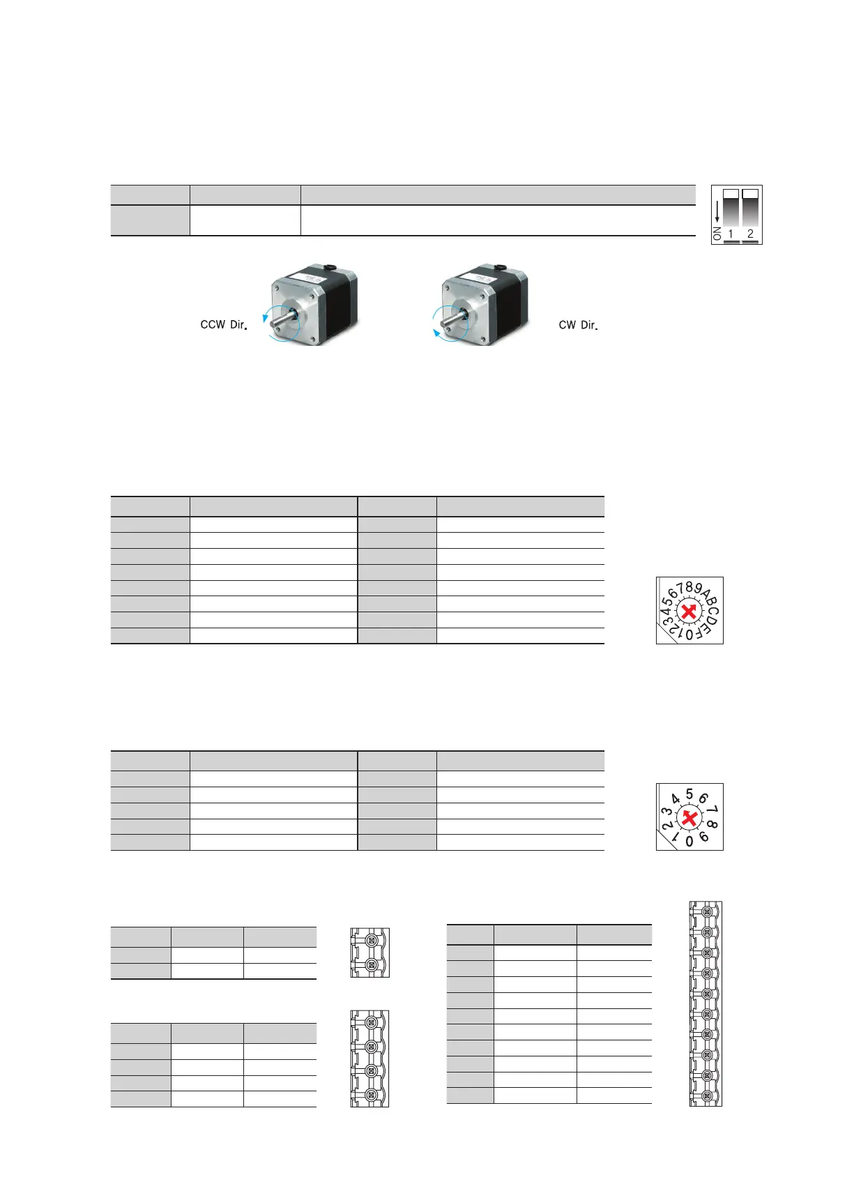
Direction setting
switch: ON
Direction setting
switch: OFF
15.3 Rotational Direction Setting Switch(SW1.2)
Indication Switch Name Functions
DIR
Rotational Direction
Select Switch
Based on CW(+Dir signal) input to driver.
ON: CCW(-Direction) OFF: CW(+Direction) ※ Default: CW mode
15.4 Run Current Setting Switch(SW2)
SW2 do not used in Ezi-STEP HPB
Position Pulse/Revolution Position Pulse/Revolution
0 500 8 6,400
1 1,000 9 8,000
2 1,600 A 10,000
*1
3 2,000 B 20,000
4 3,200 C 25,000
5 3,600 D 36,000
6 4,000 E 40,000
7 5,000 F 50,000
Position STOP Current (%) Position STOP Current (%)
0 10 5 60
1 20 6 70
2 30 7 80
3 40 8 90
4 50
*1
9 100
15.5 Resolution Setting Switch(SW3)
15.6 Stop Current Setting Switch(SW4)
*1 : Default : 10,000
*1 : Default : 50%
The Number of pulse per revolution.
Stop Current means the motor current value automatically set in 0.1 sec after motor stops. This is to prevent the overheart of a motor when
the motor is uder long time idling. The unit of the selection value is a percentage.
15.8 Motor Connector(CN2)
NO. Function I/O
1 /B Phase Output
2 B Phase Output
3 /A Phase Output
4 A Phase Output
15.7 Power Connector(CN1)
NO. Function I/O
1 GND Input
2 40~70VDC Input
15.9 Signal Connector(CN3)
NO. Function I/O
1 F.GND ----
2 EXT_GND Input
3 Alarm Output
4 Run/Stop Output
5 Alarm Reset Input
6 EXT_24VDC Input
7 CCW-(Dir-) Input
8 CCW+(Dir+) Input
9 CW-(Pulse-) Input
10 CW+(Pulse+) Input
 Loading...