www.fastech.co.kr - 29
17.4 Pulse Input Setting Switch(SW1.6)
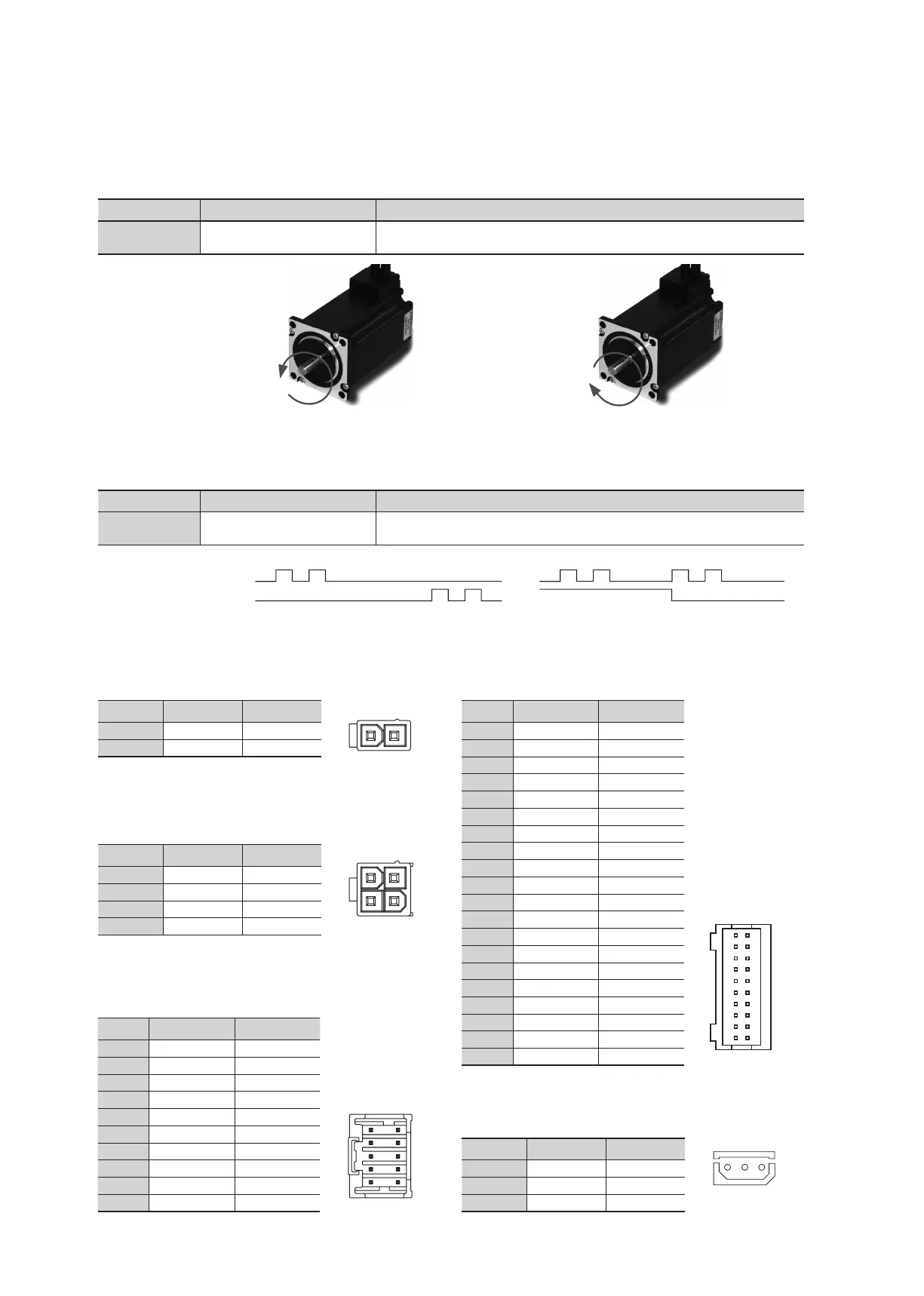
17.3 Rotational Direction Setting Switch(SW1.5)
Indication Switch Name Functions
2P/1P
Selecting pulse
input mode
Selectable 1-Pulse input mode or 2-Pulse input mode as Pulse input signal.
ON: 1-Pulse mode OFF: 2-Pulse mode ※ Default: 2-Pulse mode
Indication Switch Name Functions
DIR
Switching Rotational
Direction
Based on CW(+Dir signal) input to driver.
ON: CCW(-Direction) OFF: CW(+Direction) ※ Default: CW mode
CW(Pulse) Pin
CCW(Dir) Pin
Rotational Direction CW CWCCW CCW
2-Pulse Mode 1-Pulse Mode
Direction setting
switch: ON
CCW Dir
Direction setting
switch: OFF
CW Dir
17.6 Motor Connector(CN3)
NO. Function I/O
1 A Phase Output
2 B Phase Output
3 /A Phase Output
4 /B Phase Output
17.5 Power Connector(CN4)
NO. Function I/O
1 24VDC Input
2 GND Input
17.8 Input/Output Signal Connector(CN1)
NO. Function I/O
1 A- Output
2 A+ Output
3 B- Output
4 B+ Output
5 Z- Output
6 Z+ Output
7 BRAKE- Output
8 BRAKE+ Output
9 EXT_GND Input
10 EXT_24VDC Input
11 Alarm Reset Input
12 Enable Input
13 Alarm Output
14 In-Position Output
15 O.C Input Input
16 S-GND Output
17 CW-(Pulse-) Input
18 CW+(Pulse+) Input
19 CCW-(Dir-) Input
20 CCW+(Dir+) Input
2 1
3 1
4 2
17.7 Encoder Connector(CN2)
NO. Function I/O
1 A+ Input
2 A- Input
3 B+ Input
4 B- Input
5 Z+ Input
6 Z- Input
7 5VDC Output
8 GND Output
9 F.GND ----
10 F.GND ----
2
10
1
9
19
1
20
2
17.9 Parameter Setting Communication
Connector(CN5)
NO. Function I/O
1 Tx Output
2 Rx Input
3 GND ----
1 2 3
 Loading...