FEASA LED ANALYSER
FUNCTIONAL VERSION
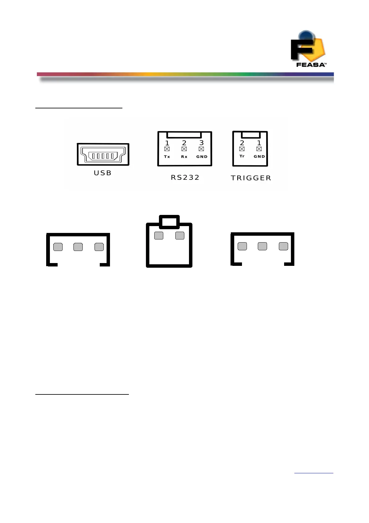
Physical Layout
Figure 6a (Front Panel).
Figure 6b (Rear Panel).
This shows the layout of the Connectors viewed from the edge of the board.
Figure 6a shows the physical layout of the Feasa x-F, x-FB and x-LT Analyser Front Panels.
Figure 6b shows the physical layout of the Feasa x-F, x-FB and x-LT Analyser Rear Panels.
These units are enclosed in an Aluminium Case. The Serial port is a 3 pin connector with the
Serial and Power cables supplied and the USB connector is the mini usb again the cable is
supplied with the unit.
Please refer to the Fixturing Guidelines Manual for connector pin out details.
USB Port Control
Connect the LED Analyser to the PC using the supplied USB cable.
Power is supplied through the USB Cable so there is no need to plug in the Power cable.
The installed Software Driver will configure the USB Port automatically.
The USB Port is configured as a Virtual Com Port and will be designated a name such as COM5,
COM6, etc.
Back to Index
15
1
2
3
D_IN
1
2
3
D_OUT
GND
5V
POWER SUPPLY
 Loading...