18
Installation
Modulator High-Powered Omni Speaker (MOD Series)
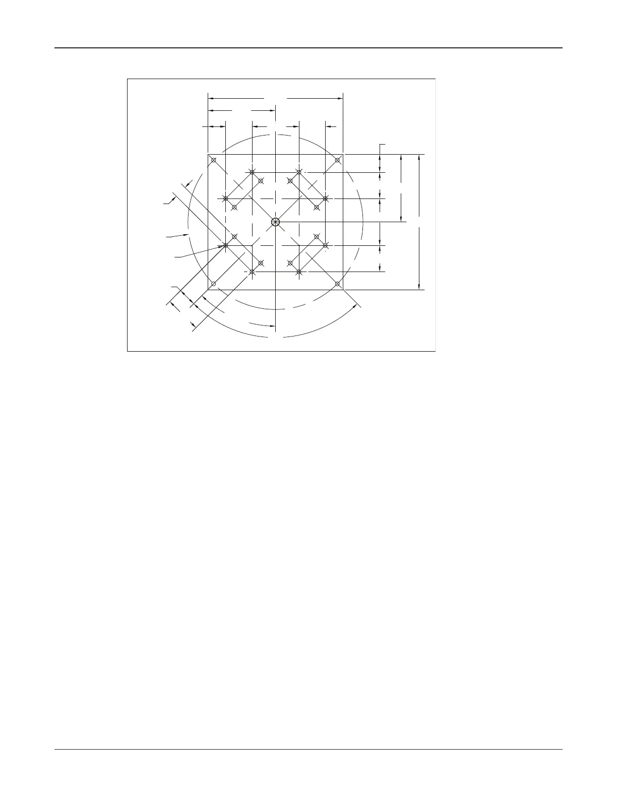
Figure 5 Siren Base Plate
291277A
3.49
9.00
3.49
3.49
2.39
18.00
90°
4X 1.62
4X 45°
4X 2.47
4X 4.94
2.39
9.00
6.233.49
18.00
6.23
Ø23.25
20X Ø0.56
Flat Surface Mounting
This installation conguration is practical when the installation site is on a at roofed
building. A weight distribution mat is often required to safely distribute the siren’s weight
on the roof. A Structural Engineer is required.
Driver Connections
Depending on the model of siren used, the number of driver connections and wire colors
will vary. This is due to the different number of drivers required for each model. See
Figures 6 and 7 for wiring and position.
Observe proper polarity when making these connections:
• The striped wire is common and goes to position 2.
• The solid colored wire is signal high and goes to position 1.
NOTE: Drivers on all Modulators except MOD1004 and MOD2008 are not assembled
due to shipping orientation.
The bottom module in the speaker array is an inactive module. This means there are
no drivers contained in the module. The next module up is called module number one.
The next one above module one is called module number two, and so forth. These are
referred to as active modules. Each active module contains four (4) drivers except the
MOD6032B has two modules with eight (8) drivers.
 Loading...