FLEX-6400/FLEX-6600 Hardware Reference Manual
Page 35 of 45
Copyright 2018 FlexRadio Systems. All Rights Reserved.
10 TRANSVERTER SETUP
Transverters allow both reception and transmission on frequencies not available in your
base FLEX-6400/FLEX-6600 radio. The transverter translates RF at one frequency to
another for both transmit and receive. Generally, the transverters will have an RF side
that is in the VHF or microwave region and an IF side in the HF or low VHF side. An
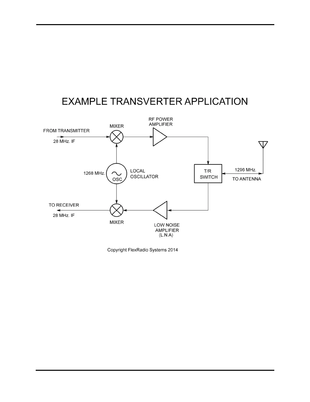
example transverter block diagram is shown below:
This transverter converts from 10m RF signals (28MHz) to 1296MHz RF signals and back.
The transverter shown in the picture has three RF connectors:
RX IF - the 10m receive port
TX IF - the 10m transmit port
RF - the RF input and output that goes to an antenna
This type of transverter is known as a “Split IF” transverter since the IF side of the
transverter utilizes both a receiver and a transmitter port. The other type of transverter
is a “Common IF” transverter where a relay internal to the transverter is used to switch a
single IF port between receive and transmit. Both the FLEX-6400 and FLEX-6600 are
capable of either Common IF or Split IF operation.
 Loading...