ProcessMeter
Loop Power Supply Mode
29
Loop Power Supply Mode
The Loop Power Supply Mode can be used for powering
up a process instrument (transmitter). While in Loop
Power Mode, the meter acts like a battery. The process
instrument regulates the current. At the same time, the
meter measures the current that the process instrument
is drawing.
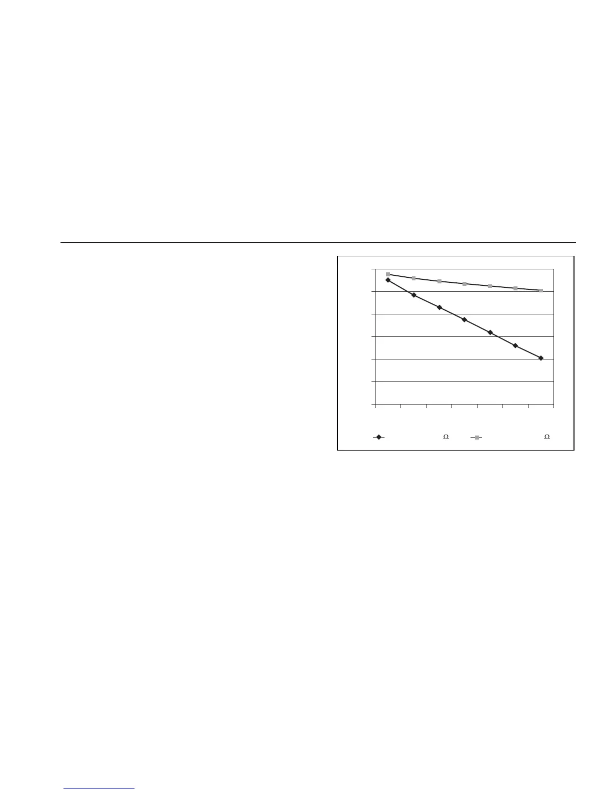
The meter supplies loop power at a nominal 24 V dc. An
internal series resistance of 250 Ω can be switched in for
communication with HART and other smart devices by
pressing J(Blue). Pressing J(Blue) again switches out
this internal resistance.
When loop power is enabled, the meter is configured to
measure mA and > 24 V dc is sourced between the mA
and A jacks. The mA jack is the common and the A jack
is at > 24 V dc. Connect the meter in series with the
instrument current loop as Figure 10 shows.
32
30
28
26
24
22
20
0 4 8 12162024
Loop voltage w/ 250
Loop voltage w/o 250
Voltage (V)
Current (mA)
anw020f.eps
Figure 9. Loop Power Voltage vs. Current

 Loading...