18
Chapter
I-General
Engine Overhaul, Inspection,
and
Repair
Runouf
Goug
e
~
Tool-lor Removing
and
Installing pilot
6603
fig.
,
4-Valve
Seat
Runout
Check-Typical
Inspect
the
valve
springs
for
signs
of
failure.
Check
the
valve
spring
for
proper
pressure
(fig.
11)
and
squareness
(fig.
12).
Check the
valve
spring retainers, locks, and
sleeves
for wear
or
signs of failure.
Check
the
exhaust
valve
seat
cessive
wear
(ECR
272, 302,
engines)
.
insert for
and
332
signs
of
ex-
cubic inch
Check the
valve
<item
clearance
of
each
valve
in its
respective
valve
gu
ide
as
shown
in
fig. 13.
Instal\
the
tool
on
the
valve
stem
until
ful\y
seated
and
tighten
the
the
set
screw, then permit
the
valve
to
drop
away
from
its
seat
until
the
tool
contacts
the
upper
surface
of
the
valve
guide.
Position
a dial indicator
with
a flat tip
against the center portion
of
the spherical section
of
the
tool
at
approximately
90
'
to
the
valve
stem.
Move
the
tool
back
and
forth
on
a
plane
that
paral\els
normal
rocker action and take
the
indicator reading without lift-
ing
the
tool from
the
valve
guide upper surfaces.
Divide
the
indicator
reading
by
2
(division
factor
of
the
tool)
to
obtain the actual
stem
clearance.
Check
the
valve
seat
runout
and
the
valve
seat
width
as
shown
in figs.
14
and
15.
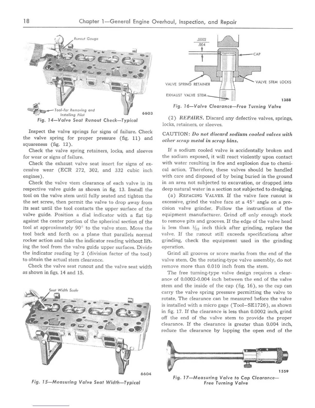
Fig.
IS-Measuring
Valve
Seat
Width-Typi
cal
.0002
VA
L
VE
STEM
L
OCKS
EXHAUST
VALVE
STEM
__
.....
z....
13
88
Fig.
J6
- Va
lve
Cleara
nce-
Fr
ee
Tu
rni
ng
Valv
e
(2)
REPAIRS.
Discard
any
defective
va
lves,
springs
,
locks, retainers, or
sleeves.
CAUTION:
Do
not
discard
sodium
coo
l
ed
va
lves with
other
scrap
metal
in
scrap
bi
ns.
If
a sodium
cooled
va
l
ve
is acc
identa
lly broken and
the sodium exposed, it will react violently upon contact
with water
reSUlting in fire and
explosio
n
due
to
chemi-
cal
action.
Therefore,
these
va
l
ves
sho
ul
d
be
handl
ed
with care and disposed
of
by
being
buried in
the
ground
in an area not
subjected
to
excava
tio
n,
or dropped into
deep
natural water in a
sec
tion not subj
ec
ted
to
dredging.
(a)
REFACING
VALVES.
If
the
va
l
ve
f
ace
ru
n
out
is
excessive, grind
the
valve
face
at
a
45
° angle on a
pr
e-
cision
valve
grinder.
Follow
the
instructions
of
the
equipment
manufacturer. Grind off
only
enough stock
to
remove
pits and grooves.
If
the
edge
of the val
ve
head
is less than
%2 inch thick after
gr
inding, repl
ace
the
valve.
If
the
runout still
exceeds
specifications after
grinding, check the
equip
m
ent
used in the
gr
in
ding
operation.
Grind all grooves or score marks from
the
end
of
the
valve
stem. On
the
rotating-
type
valve
assembly,
do
not
re
move
more than
0.010
inch from the stem.
The
free turning-type
valve
design requires a clear-
ance
of
0.0002-0.004
inch
between
the
end
of
the
va
l
ve
stem
and
the
inside
of
the
cap
(fig. 1
6),
so
the
cap
ca
n
carry
the
valve
spring pressure permitting the val
ve
to
rotate.
The
clearance can
be
meas
ured before
the
valve
is
installed
with
a
micro
gage
(Too
I
-SE
I
726),
as
show
n
in
fig.
1
7.
If
the
clearance
is less
th
an
0.0002
in
ch, grind
off
the
end
of
the
va
l
ve
stem
to
provide the proper
clearance.
If
the clearance is greater than 0
.004
inch,
reduce the clearance
by
lapping the open end
of
the
Fig. J
7-
Me
asuring Val
ve
to
Cap
Cl
earance-
Free Turning
Valve
1559

 Loading...