EasyManuals Logo

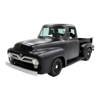
Ford 1956 Truck User Manual

Ford 1956 Truck
32 pages
To Next Page IconTo Next Page
To Previous Page IconTo Previous Page
Page #25 background imageLoading...
Page #25 background image
Section
6-
Timing Chain
and
Sprockets, Timing
Gears,
and
Camshaft
23
this position.
Make
sure
the
push
rod
is in
the
tappet
socket,
then
install
a
dial
indicator
in
such
a
manner
as
to
have
the
actuating
point
of
the
indicator
in
the
push
rod
socket
and
in
the
same
plane
as
the
push
rod
move-
ment
(fig.
25).
Rotate
the
engine
slowly
until
the
tappet
is
on
the
heel
of
the
cam
lobe.
Zero
the
dial
indicator,
then
continue
to
rotate
the
engine
slowly
until
the
pU'ih
rod
is in
the
fully
raised
position.
Compare
th
e
total
lift
recorded
on
the
indicator
to
specifications.
Continue
to
rotate
the
engine
until
the
indicator
reads
zero.
This
later
step
is a
check
on
the
accuracy
of
the
original
indicator
reading.
(2)
INSPECTION.
Thoroughly
check
the
camshaft
for cracks.
Ex
amine
the
lobes
for
pitting,
scoring,
and
signs
of
abnormal
wear.
Check
the
lobes
with
a
microm-
ete
r.
Suspected
worn
lobes
should
be
compared
with
a
good
lobe
to
be
sure
diagnosis
is
correct.
Measure
the
journal
diameter
for
wear
and
out-of-roundness.
Measure
the
I.D. of
the
camshaft
bearings.
If
the
clearances
are
excessive
the
cam
and/or
cam
bearings
should
be
re-
placed
.
Check
the
fuel
pump
eccentric
for
wear.
(3)
Rt:PAIRS.
Replace
all
camshafts
that
are
damĀ·
aged
beyond
repair.
Remove
light
scuffs, scores,
or
nicks
with
a
hard
Arkansas
stone,
then
polish
with
crocus
cloth
.
The
lobe
wear
characteristics
may
result
in
pitting
in
the
general
area
of
the
nose
portion
of
the
lobe.
This
pitting
is
not
detrimental
to
the
operation
of
the
cam
if
the
initial
cam
lobe
lift
loss
has
not
exceeded
0.005
inch.
The
camshaft
will
continue
to
operate
satisfactorily
for
the
normal
life
expec
tancy
of
the
engine
without
noticeably
affecting
engine
performance.
Therefore,
cam-
sha
fts
shou
ld
not
be
replaced
unless
the
lobe
lift
loss
exceeds
the
above
specification
or
the
tappet
contact
face
shows
evidence
of
failure.
Fig.
29-Camshaft
End Play
Check-Typical
Normally,
if
the
front
journal
to
bearing
clearance
is excessive,
it
can
be
assumed
that
all
bearings
are
worn
and
need
replacement.
If
any
of
the
teeth
on
the
distributor
drive
gear
are
broken
or
worn,
it
will
be
necessary
to
replace
the
camshaft.
(4)
CAMSHAFT
END
PlAY
CHECK.
Push
the
camshaft
toward
the
rear
of
the
engine
.
Place
a
dial
indicator
point
against
a
suitable
surface
on
the
front
end
of
the
camshaft
assembly
(fig.
29).
Set
the
dial
to
zero,
then
pull
the
camshaft
forward
and
release
it.
Compare
the
dial
reading
with
specifications
.
If
the
end
play
is
excessive,
check
the
spacer
for
correct
installation.
Replace
the
thrust
plate
and/or
spacer
if
necessary.
7. FLYWHEEL, CRANKSHAFT,
AND
MAIN BEARINGS
Procedures
for
the
inspection
and
repair
of
these
components
are
given
here.
In
addition,
procedures
for
fitting
main
bearings,
thrust
bearing
alignment,
and
replacing
the
rear
main
bearing
crankshaft
oil
seal
are
given.
a. Flywheel.
The
flywheel
and
ring
gear
are
a
shrink
fit
and
are
replaceable
as
separate
parts
.
(1)
INSPECTION.
Check
the
flywh
eel
face
.unout
with
a
dial
indic
a
tor
(fig.
30).
Be
sure
to
hold
the
fly.
whee
l full
forward
or
rearward
so
that
the
crankshaft
end
play
will
not
be
indicated
as
flywheel
runout.
If
the
runout
is excessive,
remove
the
flywheel,
and
check
the
runout
of
the
crankshaft
mounting
flange.
It
will
be
necessary
to
remove
the
crankshaft
if
the
flange
requires
machining.
Inspect
the
ring
gear
for
worn,
chipped
or
cracked
teeth.
Check
the
ring
gear
runout
as
indicated
in
fig. 31.
(2)
REPAIRS.
If
the
flywheel
runout
is
excessive
and
the
flange is
not
at
fault,
replace
or
machine
the
flywheel.
Machine
the
friction
surface
of
the
flywheel
if
it
is
scored
or
worn.
If
it
is
necessary
to
remove
more
than
0.045
inch
of
stock
from
the
original
thickness,
replace
the
flywheel.
If
the
ring
gear
teeth
are
damaged
and
unfit
for
further
use,
or
if
the
runout
is
excessive,
replace
the
ring
gear
as
follows:
Heat
the
defective
ring
gear
with
a
blow
torch
on
the
engine
side
of
the
gear,
then
knock
it
off the flywheel.

Table of Contents

Questions and Answers:

Question and Answer IconNeed help?

Do you have a question about the Ford 1956 Truck and is the answer not in the manual?

Ford 1956 Truck Specifications

General IconGeneral
BrandFord
Model1956 Truck
CategoryAutomobile
LanguageEnglish

Related product manuals